Did you read disclaimer ? Then let’s go.
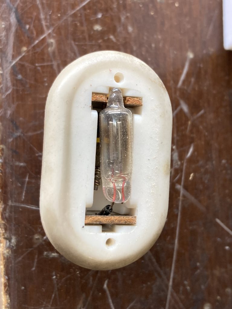
Neon bulb is hard to find. You can get this kind @ Mouser:
- VCC A2B (original size “0.244×0.750”) + standard 100k 1/4W
- VCC A1B (smaller)/2ML (even smaller) + standard 220k 1/4W
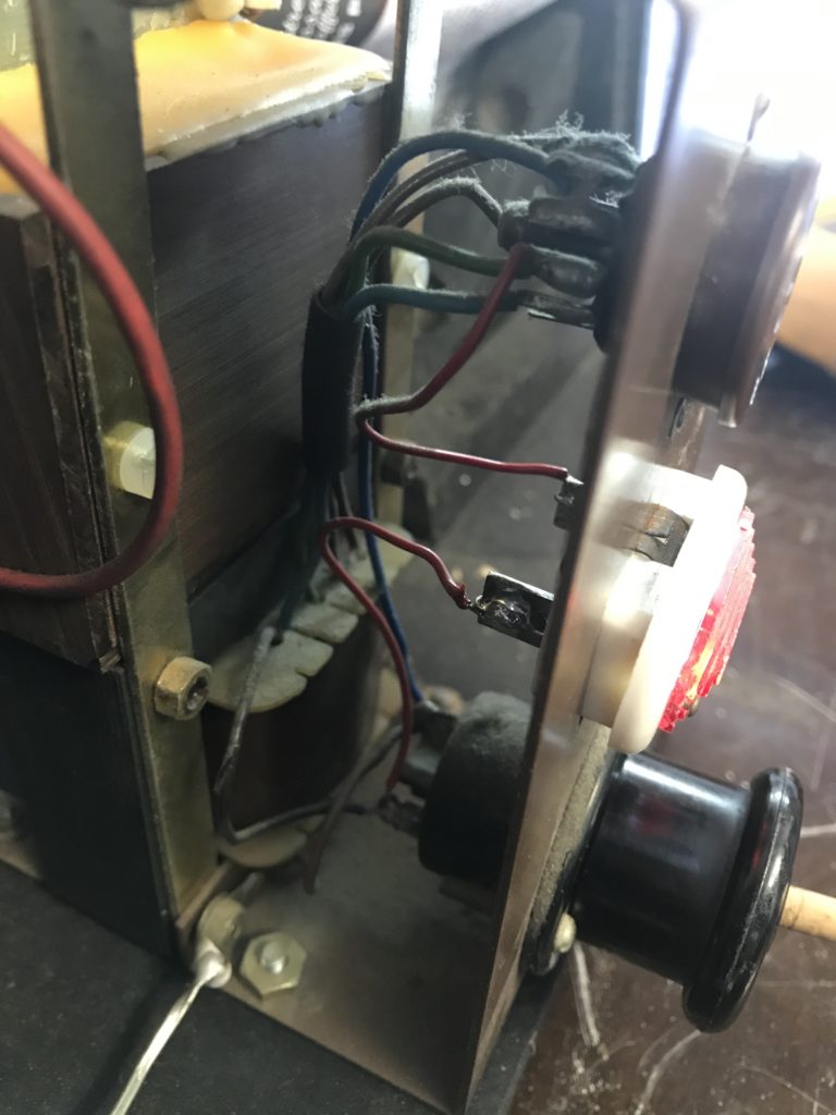
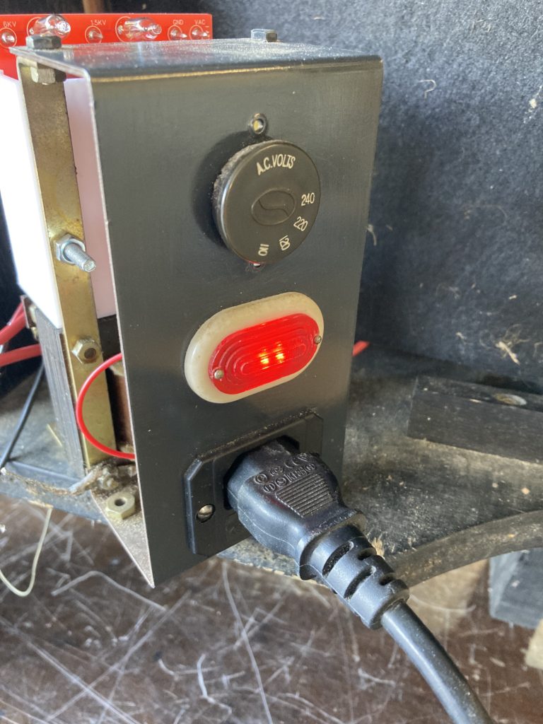
But why not replacing it with a long lasting LED ? Supply for the light was measured at about 110V AC, with EHT powered at 220V AC. Thus, as you can guess, this comes from an output of the transformer.
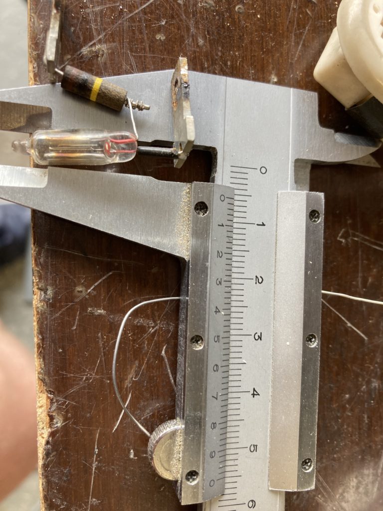
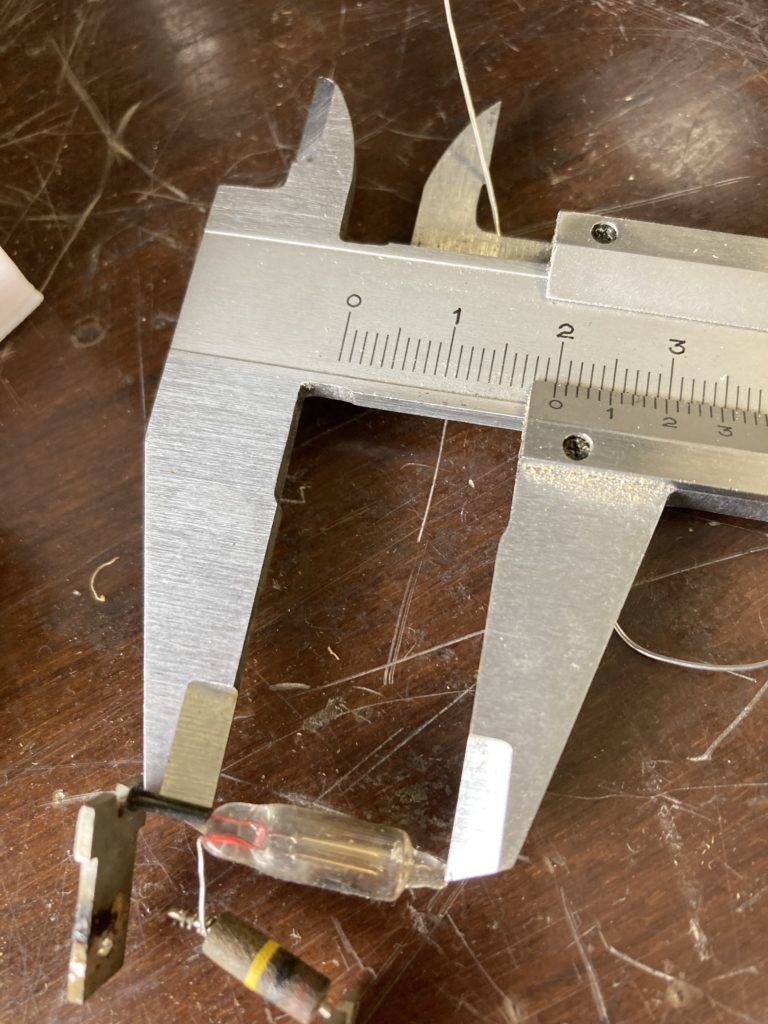
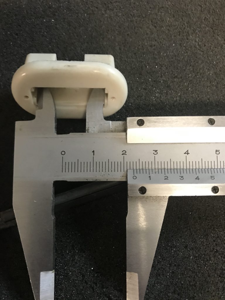
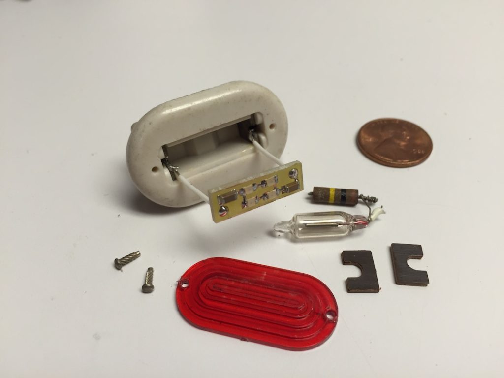
Tricky part is that the new solution must fit inside existing package. Max square size inside this package is 6.8×22.8mm. Take some margin: it may vary from one sample to another.
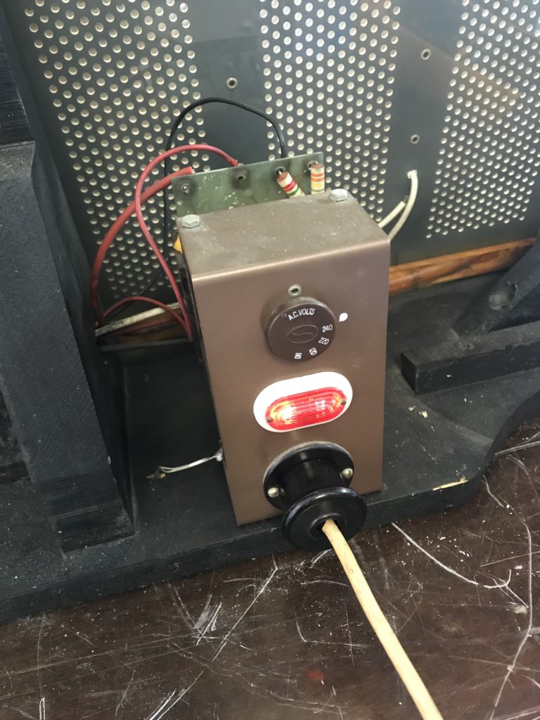
For information, outside is 23.5×38.8mm, while hole size in chassis is between 29.8×15.8mm and 30x15mm.
Version 1 (exploratory work)
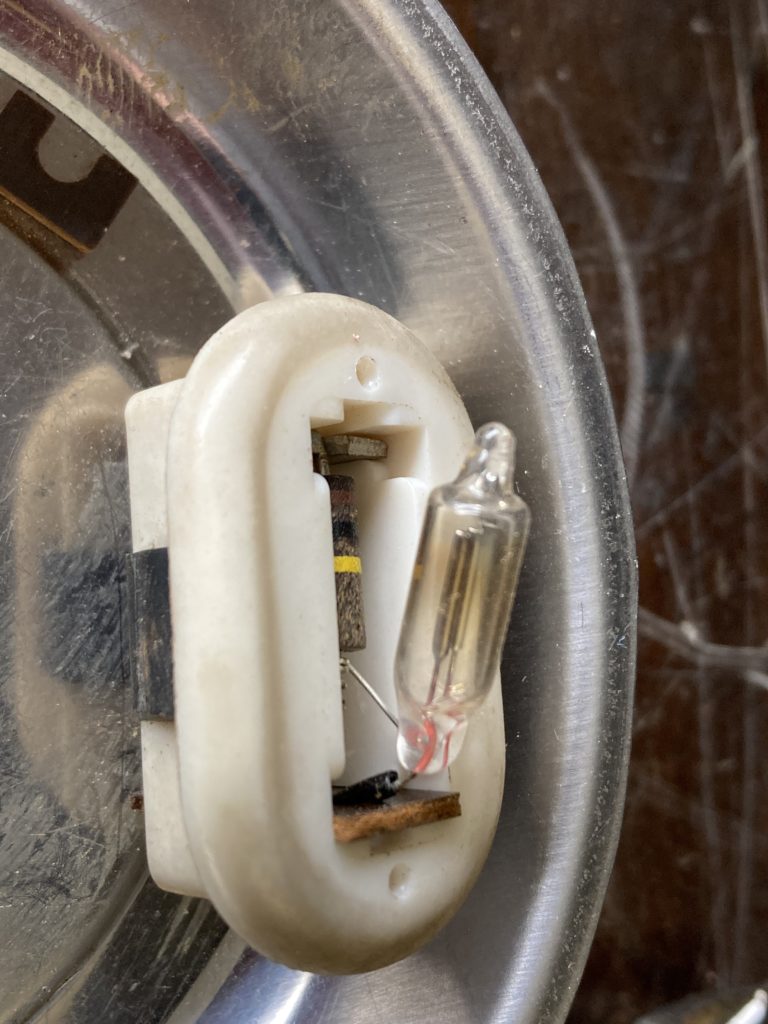
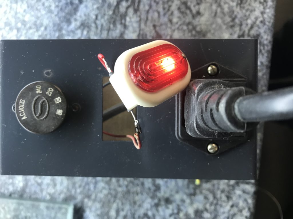
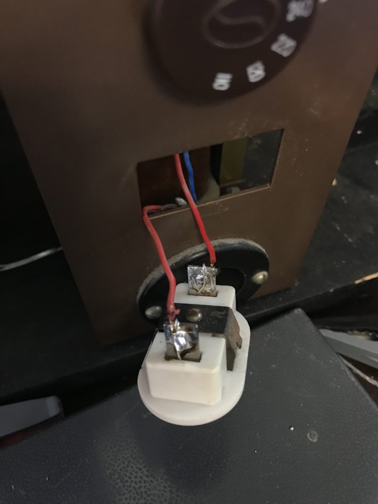
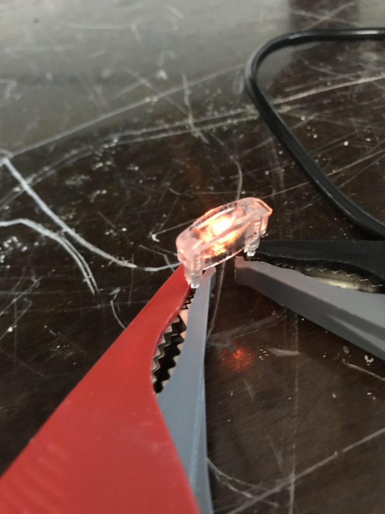
There are a great deal of tutorials on how to connect a LED to high voltage AC. Here I will use a resistor 1W 22kOhm (that supports high voltage, contrary to 1/4W, and dissipates up to … 1W), a diode EM516 (a bit overkill but small form factor and supports HV), another resistor 1/4W 100kOhm (low voltage is not an issue for that one, the smaller size the better).
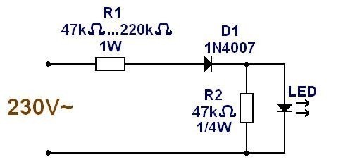
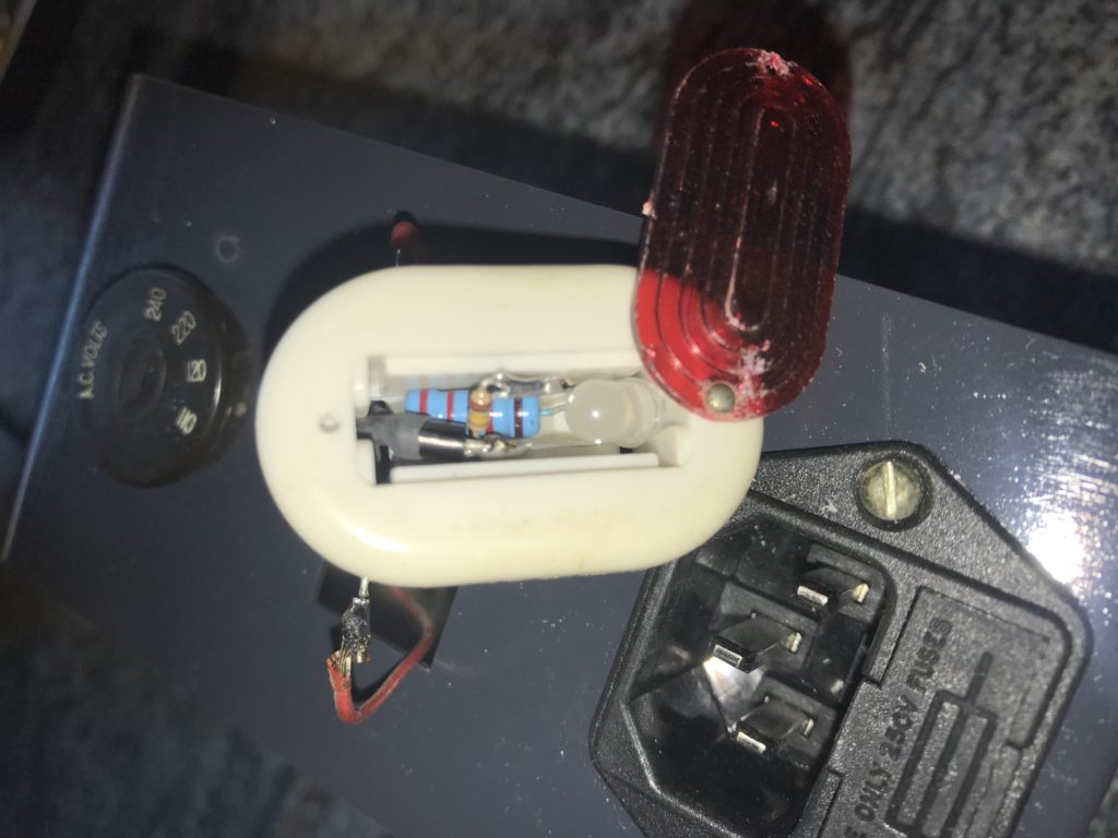
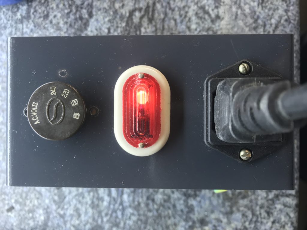
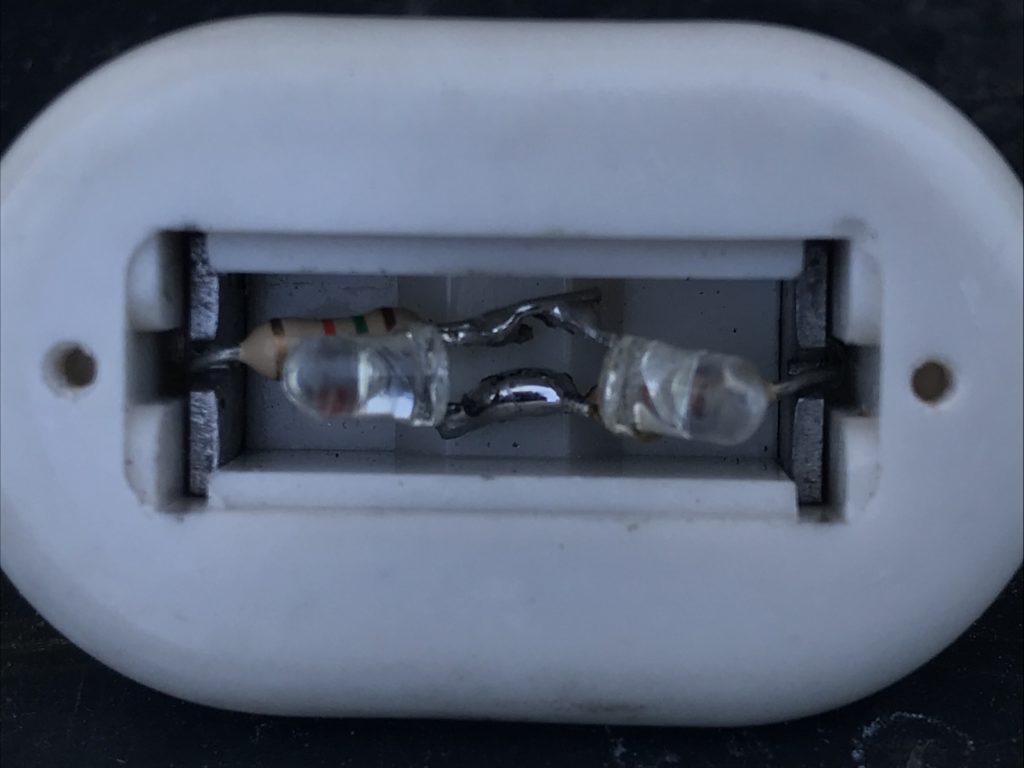
22kOhm, LED, diode are in serial (take care to polarity of diodes). 100kOhm is in parallel with LED. All this fits nicely inside existing package, as you can see on pictures.
This makes a peak current of 110*sqrt(2)/22e3 = 7mA. LED is claimed to support up to 20mA. And 110^2/22e3 / 2 = 0.275W in main resistor which is far below 1W (but 1W is nevertheless required for high voltage). Note the “/ 2” which comes from the fact that the LED passes only half of the time. HV diode + 100kOhm are there only to handle high reverse voltage, avoiding LED to support it.
If you don’t care about keeping original design, easiest solution is probably to get this reference if you can find it: Arcolectric C0430 R 28.6*14.1mm 110V Red. It should easily fit into existing hole 30*15mm (on another sample, I measured 29.8×15.8mm: it may slightly vary).
Note that very late versions of ESL 57 have a different design (Arcolectric ?):
For those who want to optimize still further, here is solution from Sheldon Stoked (https://www.quadesl.com), based on SMD components.
Version 2 (recommended)
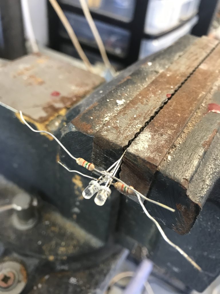
Let’s optimize version 1 by using smaller resistors (1/4W) and only LEDs (no more standard diodes). But twice as much for both devices. Use only small size LEDs: 3mm.
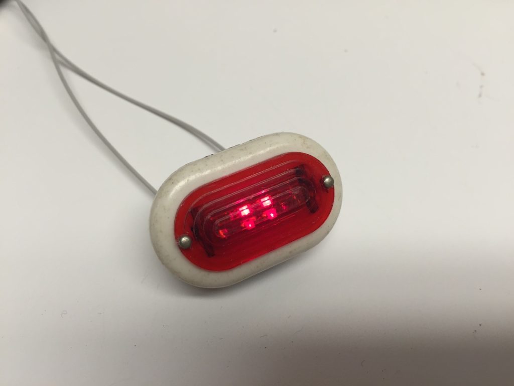
The 2 LEDs will be installed upside down to protect each other against reverse voltage. The 2 resistors – 15kOhm each – will be installed in serial mode, to halve voltage applied on each of them. Peak current will be 110*sqrt(2)/30k=5.2mA. Average power dissipated per resistor will be 110^2/30k/2=200mW (<1/4W with a margin of 20%).
Tip: 15kOhm for resistors is a minimum. You can choose up to 39kOhm and keep decent brightness. Then, you can select a white LED to get orange light or a red LED to get a pure red light.
My preference: red LEDs and 39kOhm (2mA max).
Version 3 (just a trial)
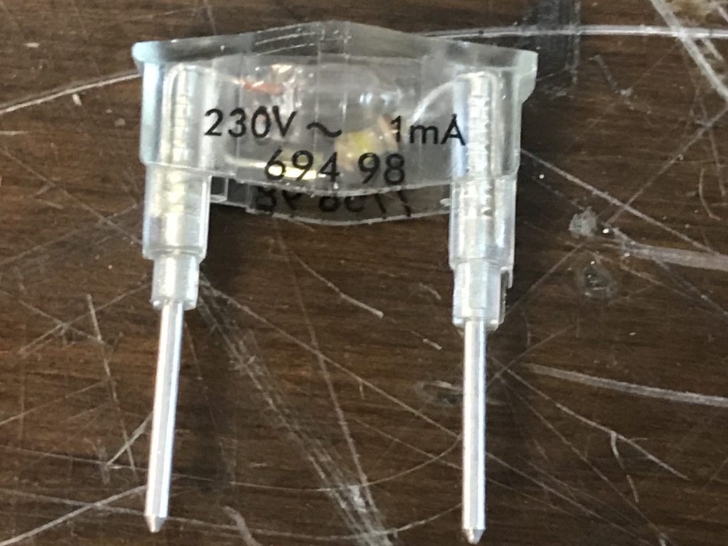
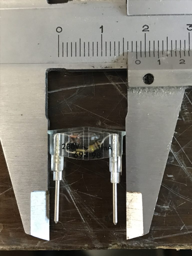
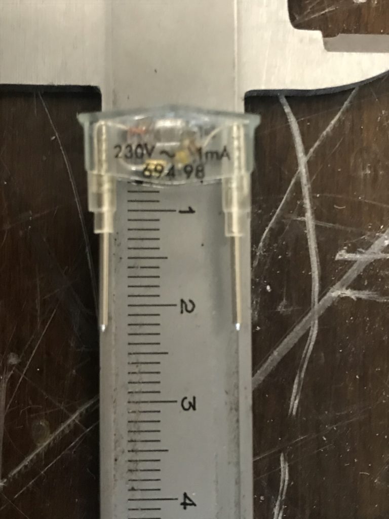
Here is a possible alternative to version 2 if you are not happy with it. I did not go to completion, but achieved basic checks on building part: “Legrand 69498” (1mA, orange).
My preference still goes to version 2. Because version 3 will be slightly more expensive and more complex, and does not use a LED.
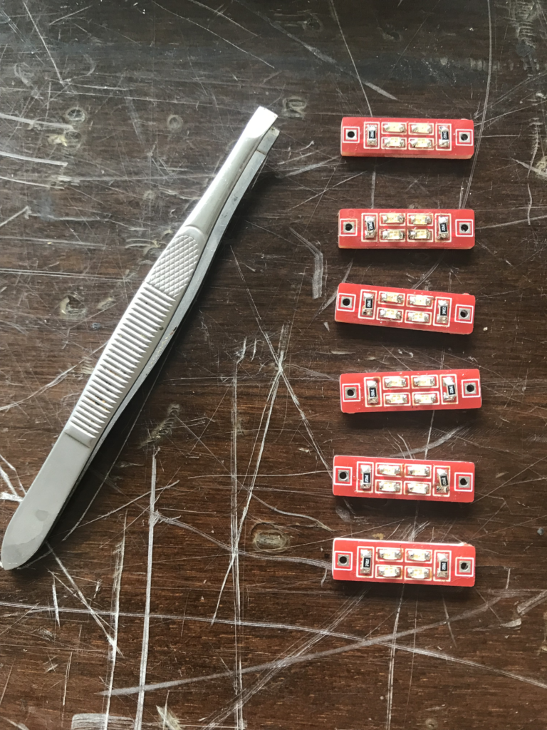
Version 4 (recommended)
PCB required ! Using SMD components.
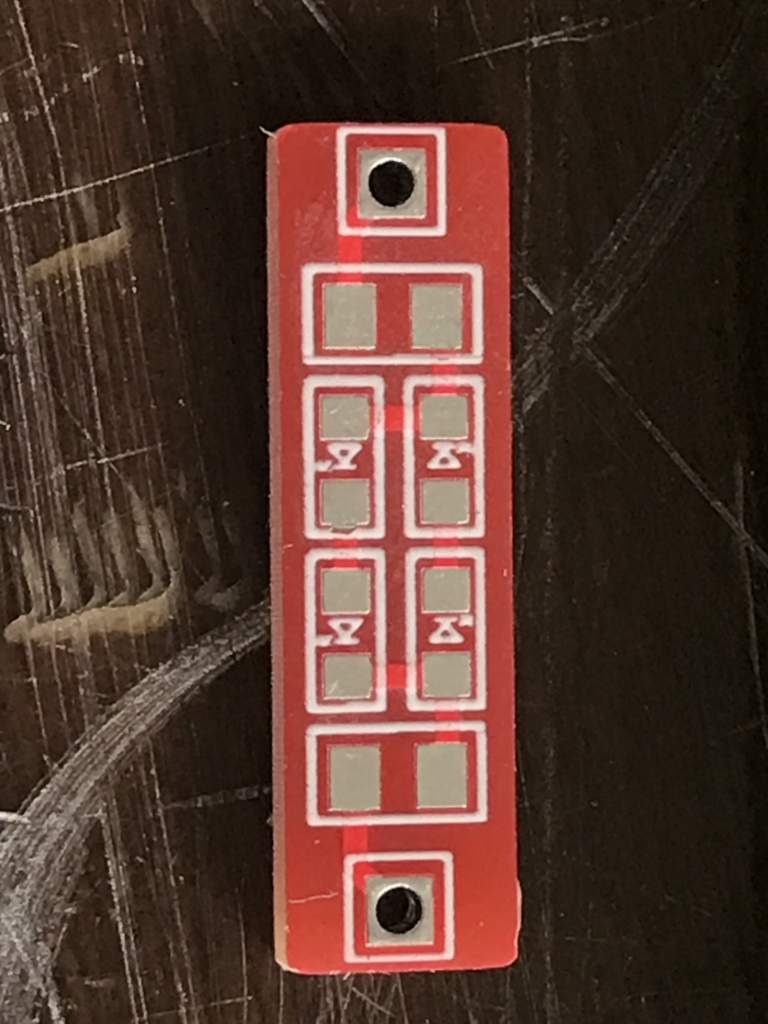
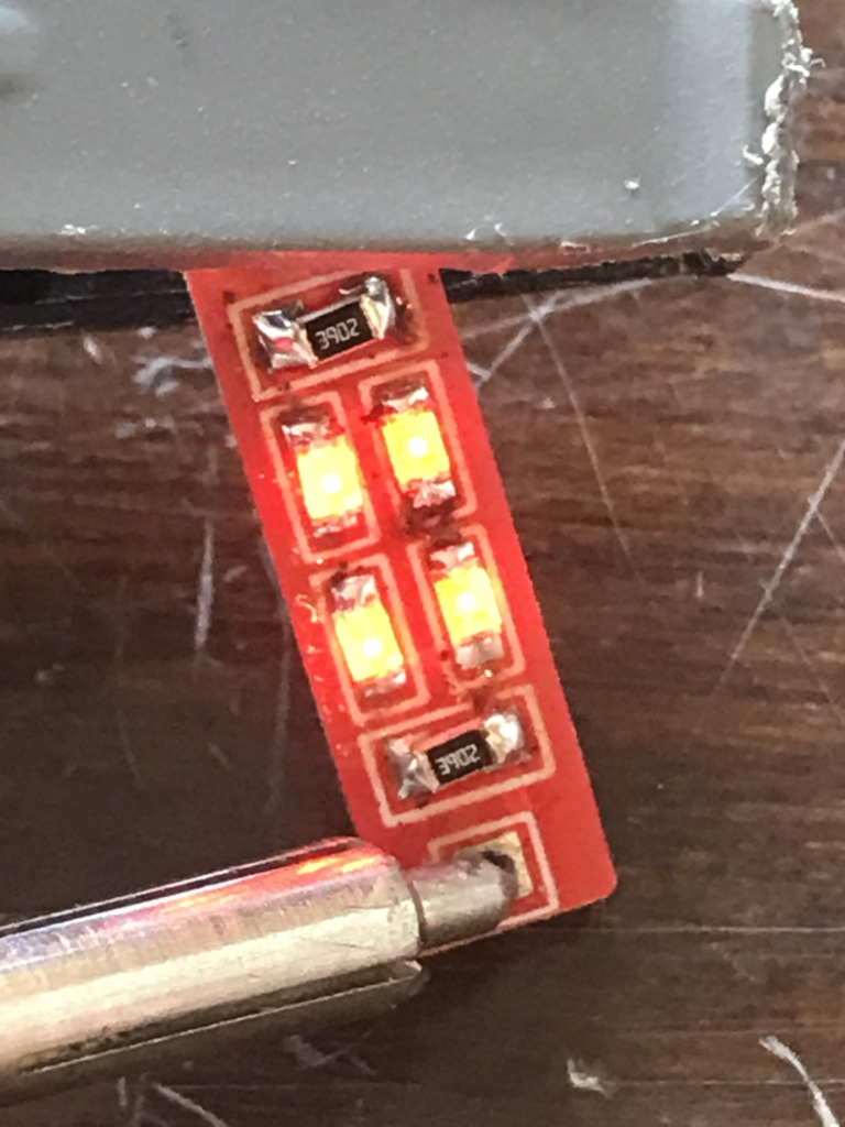
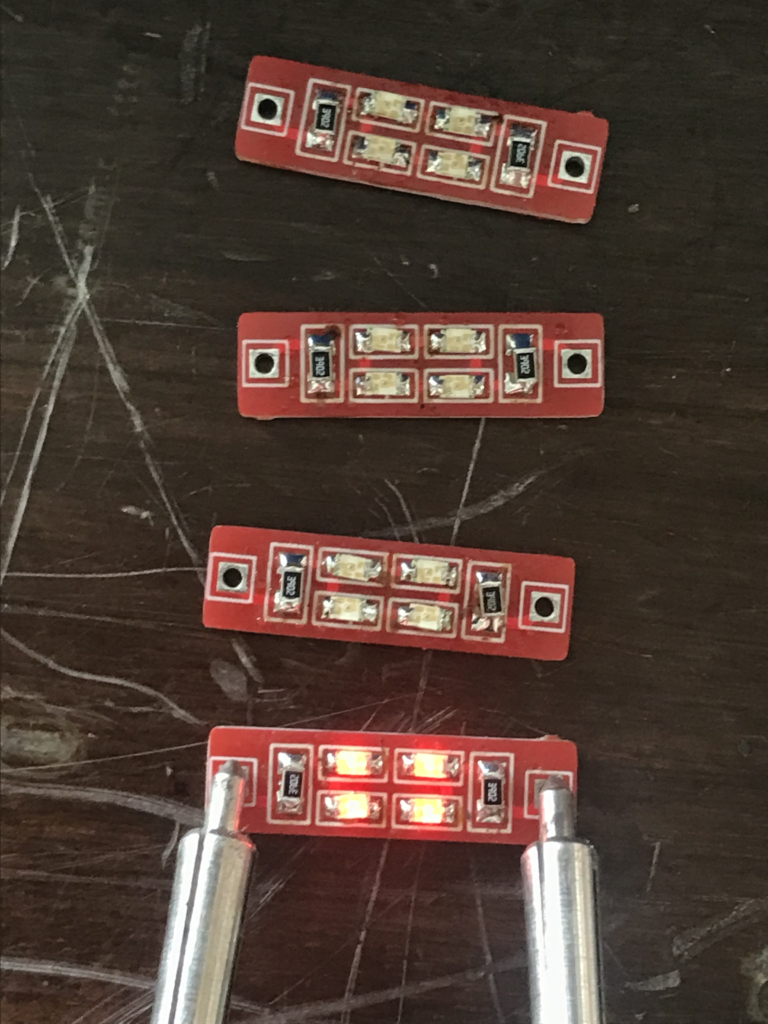
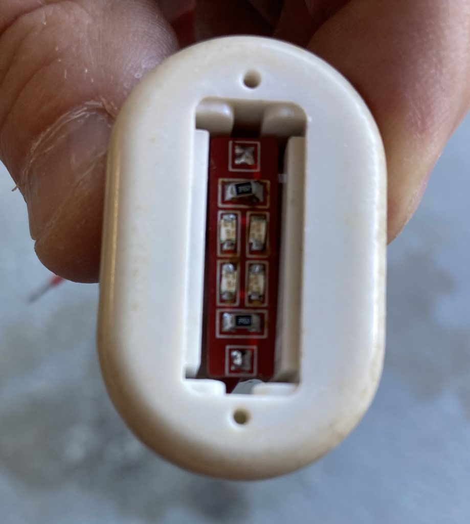
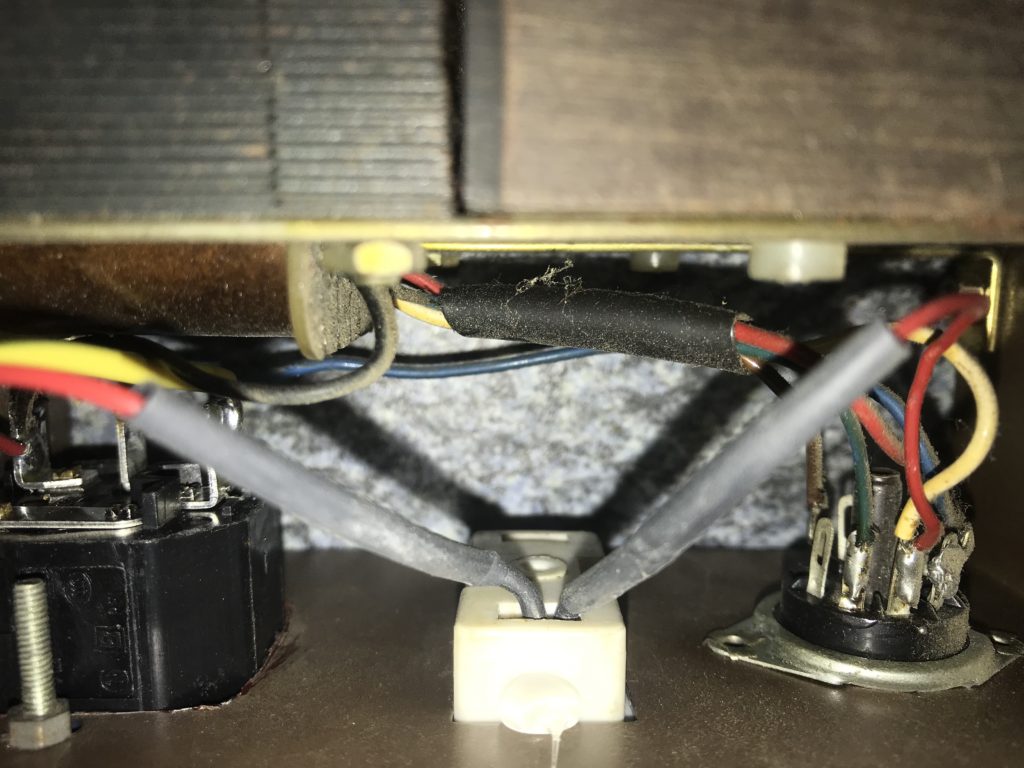
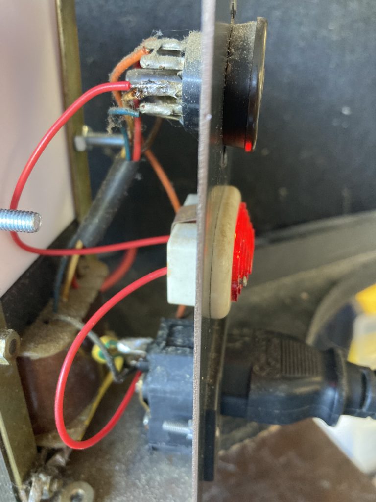
It is supposed to be installed like this: 2 rigid wires are soldered to existing terminals
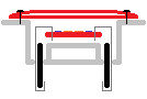
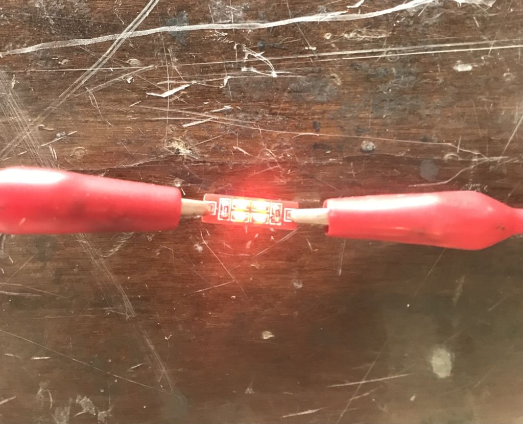
Alternative is to remove terminals and connect wires directly as illustrated below:
![]()