Introduction: serie 1 vs serie 2
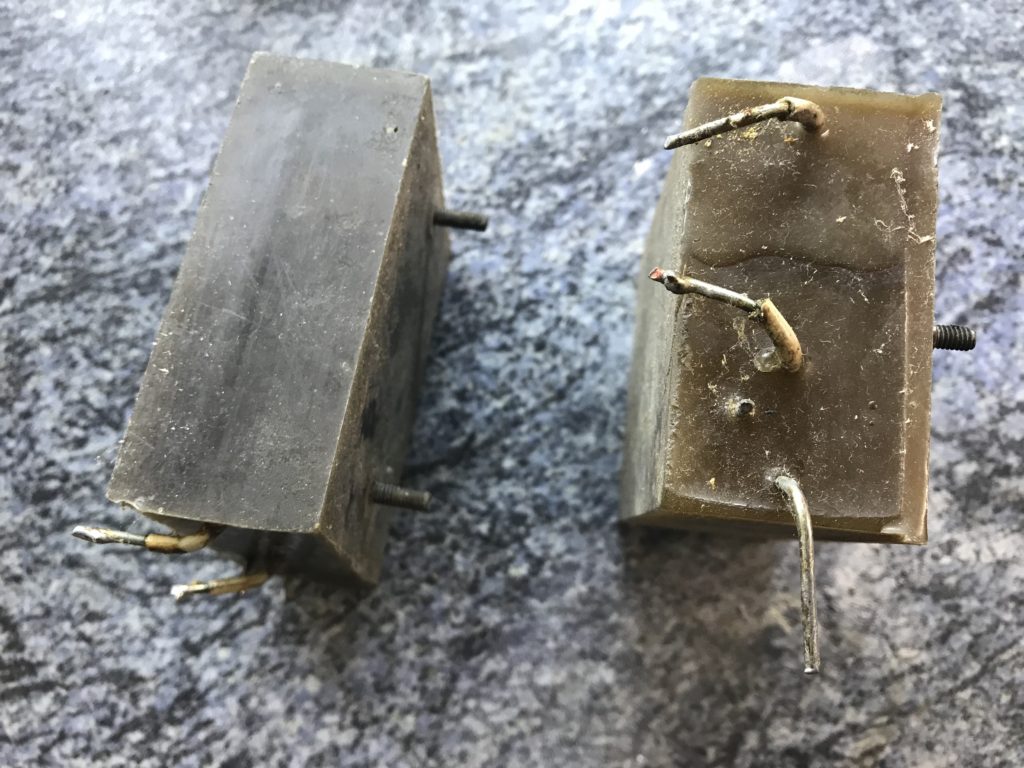
Serie 1 EHT block cannot be repaired. Serie 2 EHT block can be heated to remove wax. Here is what a serie 1 EHT block looks like. Note it is installed with connections on the left side, not on top:
Refurbishing EHT block
Look at section “part list” to order necessary parts.
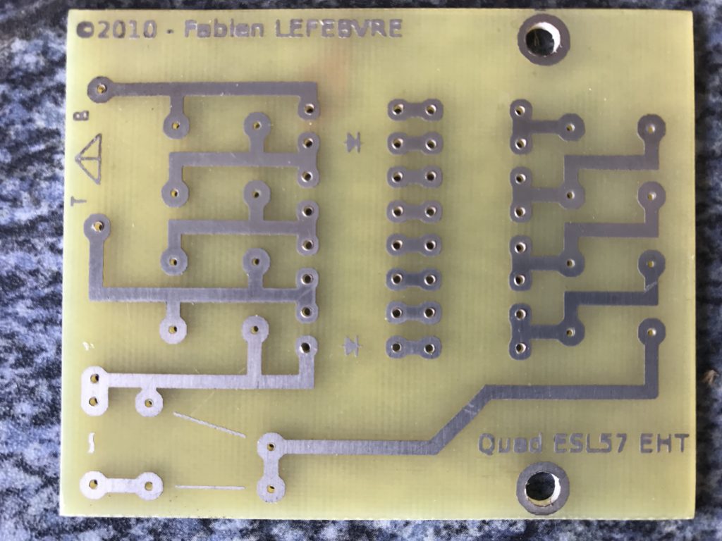
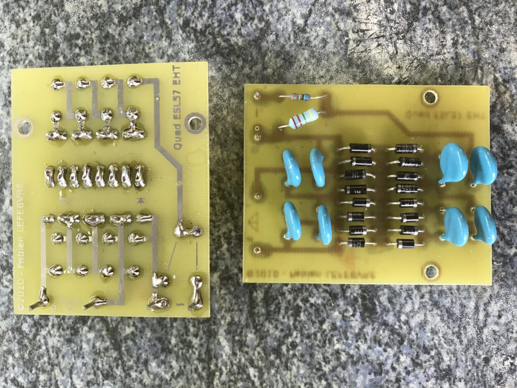
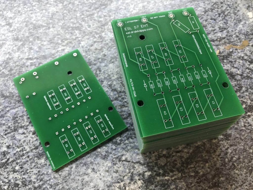
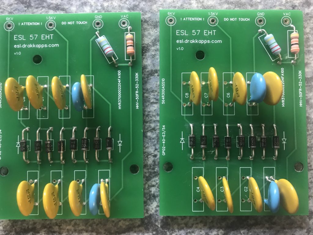
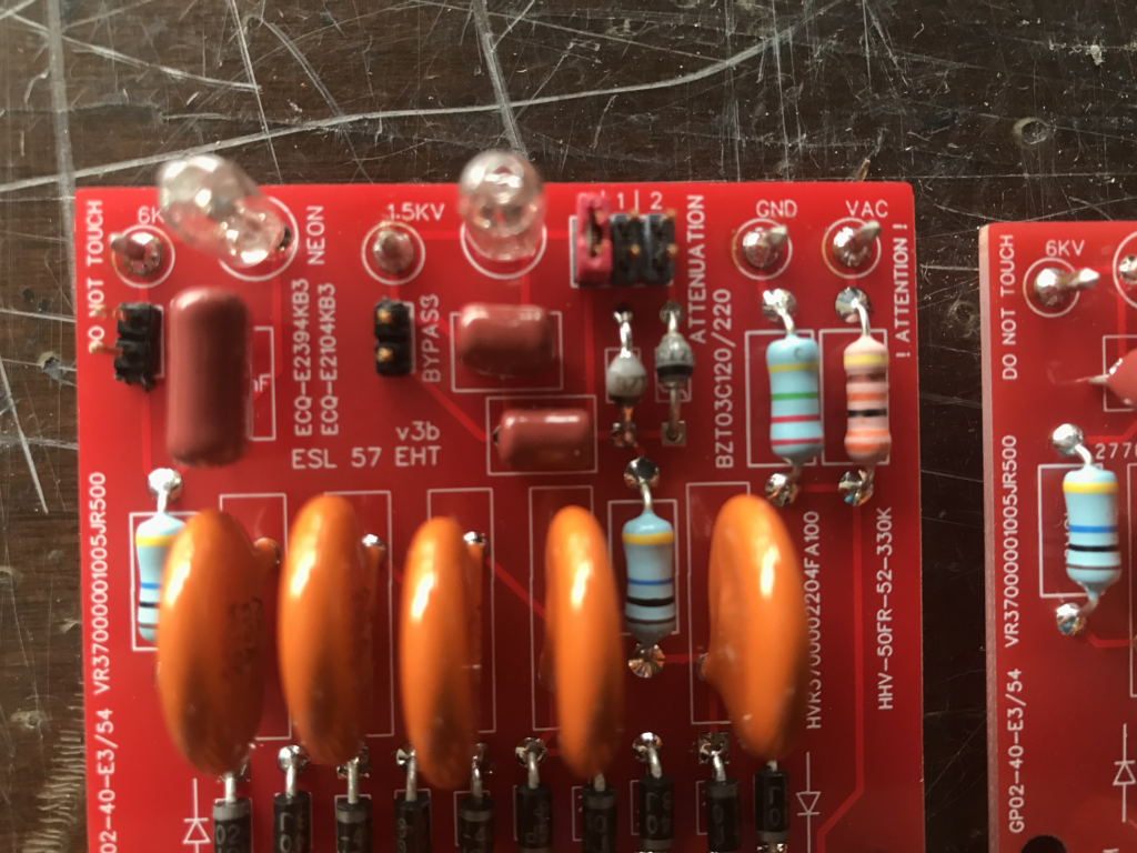
Then make your PCB, as illustrated below (reference: “SDS Labs” @ quadesl.com, page 66 here: http://quadesl.com/origRefs/quad_book.pdf):
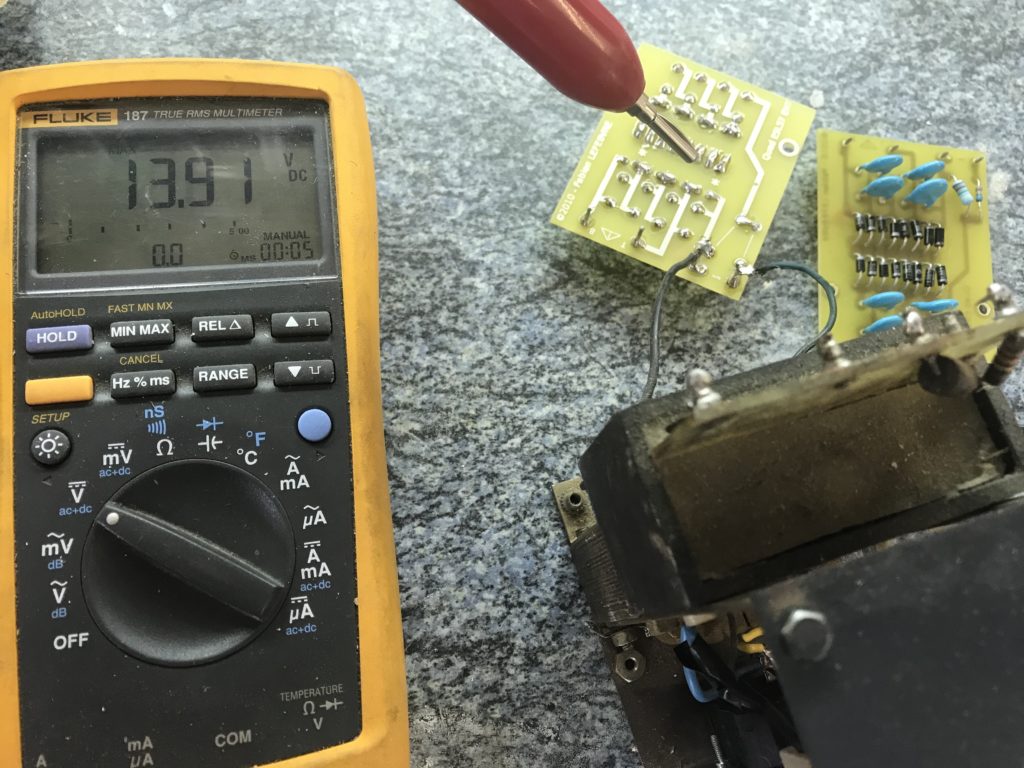
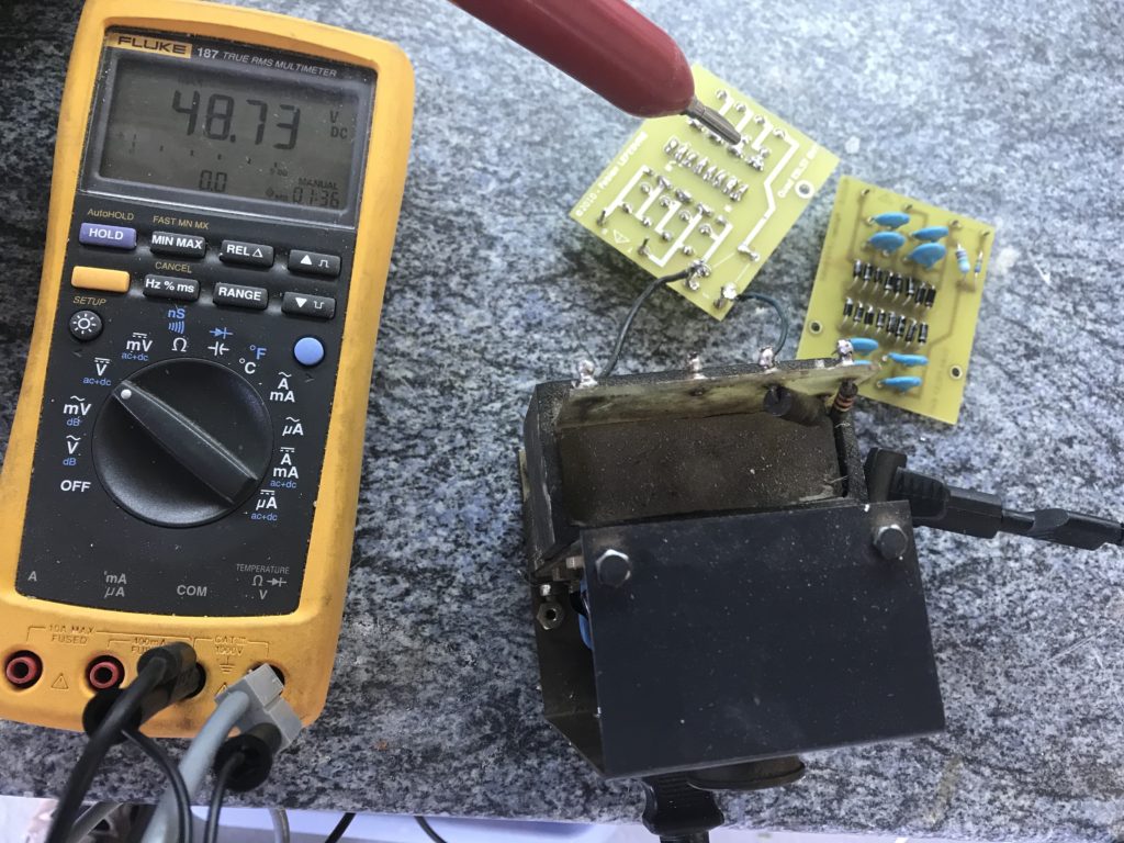
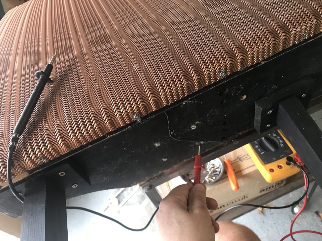
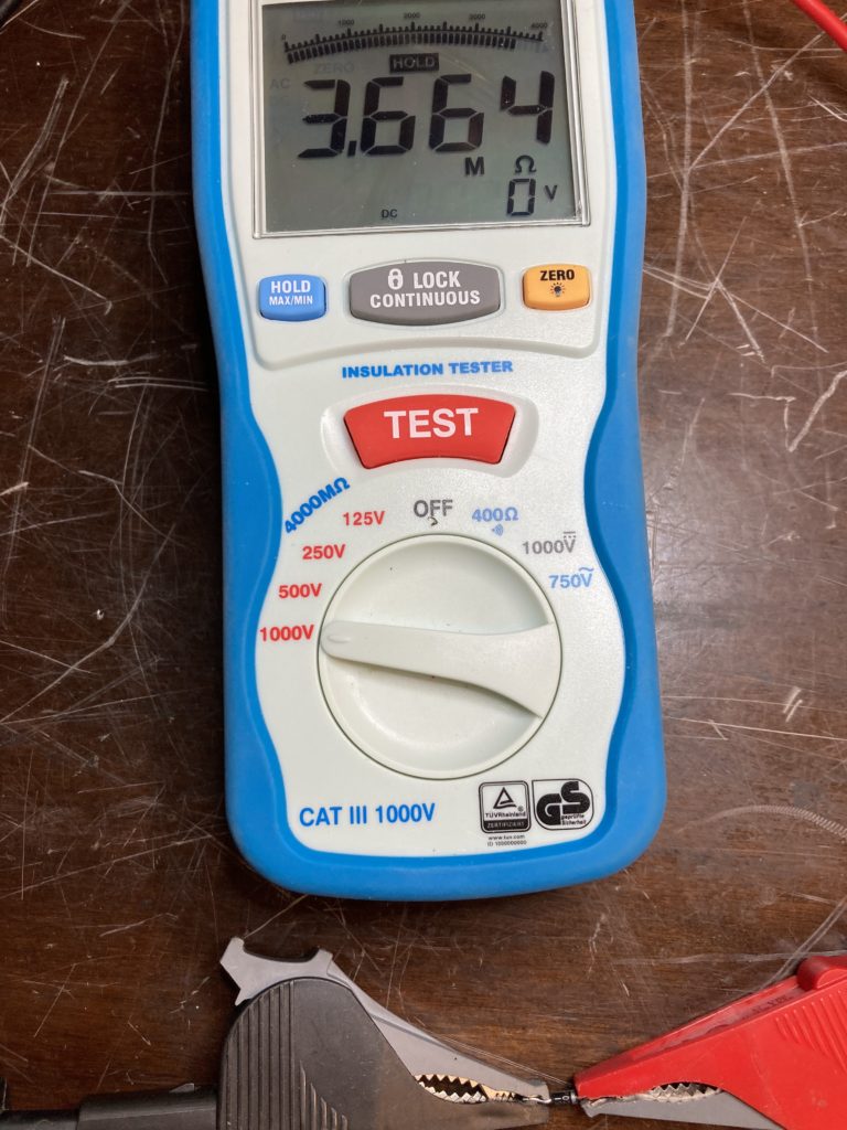
Output for bass panel may seem a bit low but not loaded with the panels themselves. Therefore, less current can go to the HV probe. The multimeter is in ‘hold max’ position. That said, shown legacy design exhibits slightly higher output on bass panel: wax has positive impact ? higher value for capacitors ? leakage in diodes ? Nevertheless, no need to worry: from reference site quadesl.org, 4.9kV is a very good value, and this increases once panels are connected. Besides, 3 instances of this re-building measure exactly the same.
Alternative PCB V1
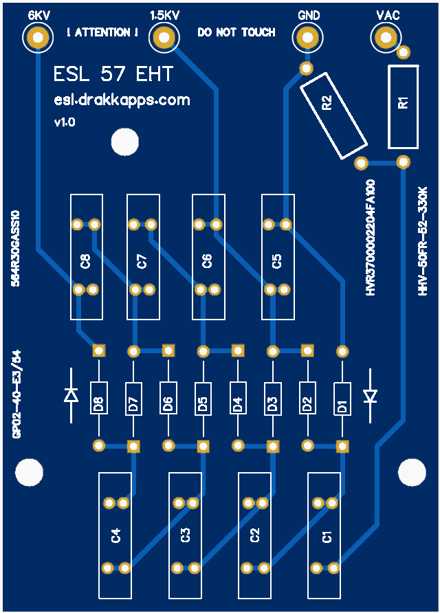
A more compact version is possible using 1 higher grade diode like GP02-40 instead of 2 standard 1N4007 diodes. Another option is to use same PCB for either version: 16 1N4007 or 8 GP02-40, but you lose benefit of compact size. Here is a proposal here below that features:
- compact size: 8 diodes only
- higher capacitance option: 8 additional capacitors can be added on the other side of the board
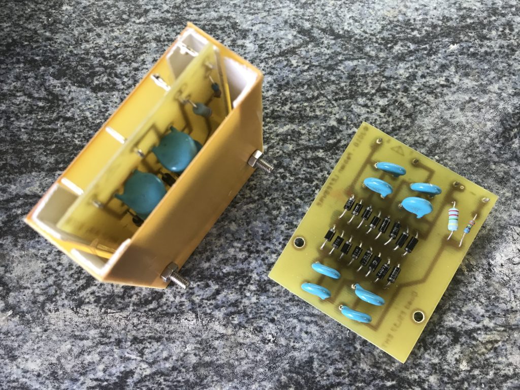
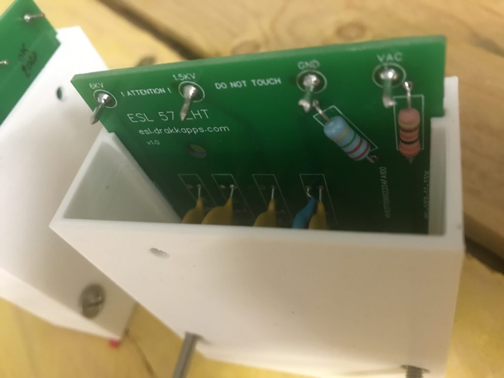
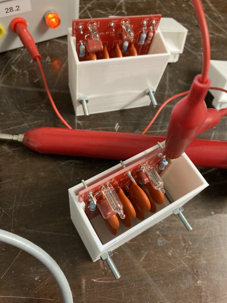
A 3D printed box can be used:
Do not forget to check grounding of the grilles:
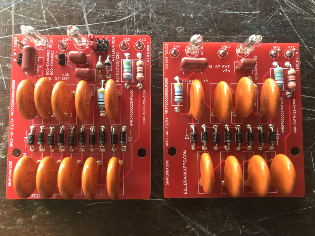
Alternative PCB V2/V3
V2 is the same shape as V1 but easier to solder and with at least one new more major feature, a blinker, as described here:
https://www.diyaudio.com/forums/planars-and-exotics/177338-quad-esl-57-hum-treble-panel.html
“the blinker consists of a small neon flash bulb, in parallel with a small film cap and a high ohmic resistor in connected in series to the bulb||cap.
The bulb may have a flashover treshold of less than 100V, the cap may be 100nF and >100V, the resistor may be 10MOhm. If the HV-supply already features a high ohmic resistor You may use that one instead.
Since the bulb is rather a shortcut when flashing you shouldn´t omit with the resistor in any case, because it reduces the current to a small and safe value and reduces the stress on the HV-supplies components. The small cap then supplies for the charging current through the bulb and it guarantees a clearly visible flash.”
Target for blink time (V2): >12s for 1 treble cell, >3s for 2 bass cells.
A second additional feature is the ability to replace the strap with a zener diode to reduce sensitivity of treble or bass cell, to balance a pair (ex: 220V on treble cell for 2 to 3 dB off).
V3 is even more compact, almost the same size as original ones. Besides, capacitor value for bass blinker was re-considered: now there is 1 blink/s/GOhm. Then, there are 2 versions: “full featured” (independent treble and bass supplies, treble attenuator, blinker bypass) and “essential”.
Target for blink time (V3): >12s for 1 treble cell, >12s for 2 bass cells.
![]()