Do-able, provided you have access to a large milling machine.
First of all, you will find tons of useful information in the file here below (“Loudspeaker and headphone handbook”), in chapter written by Baxandall (3.4).
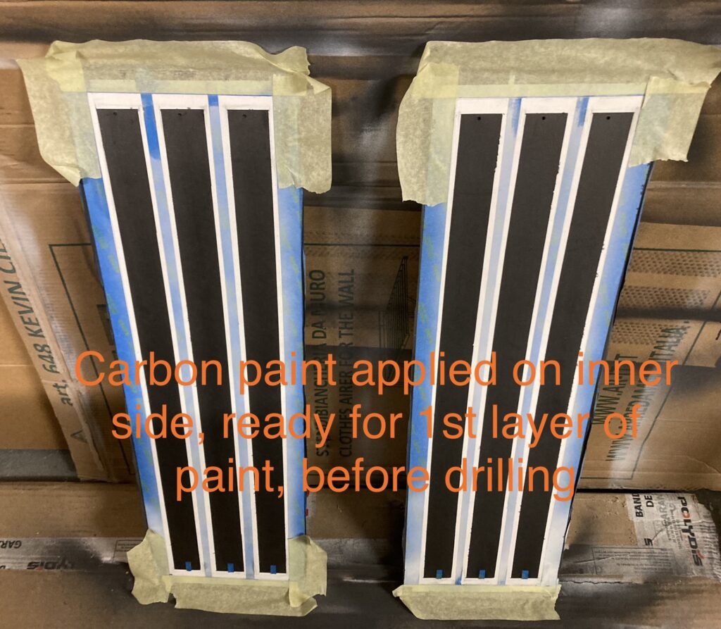
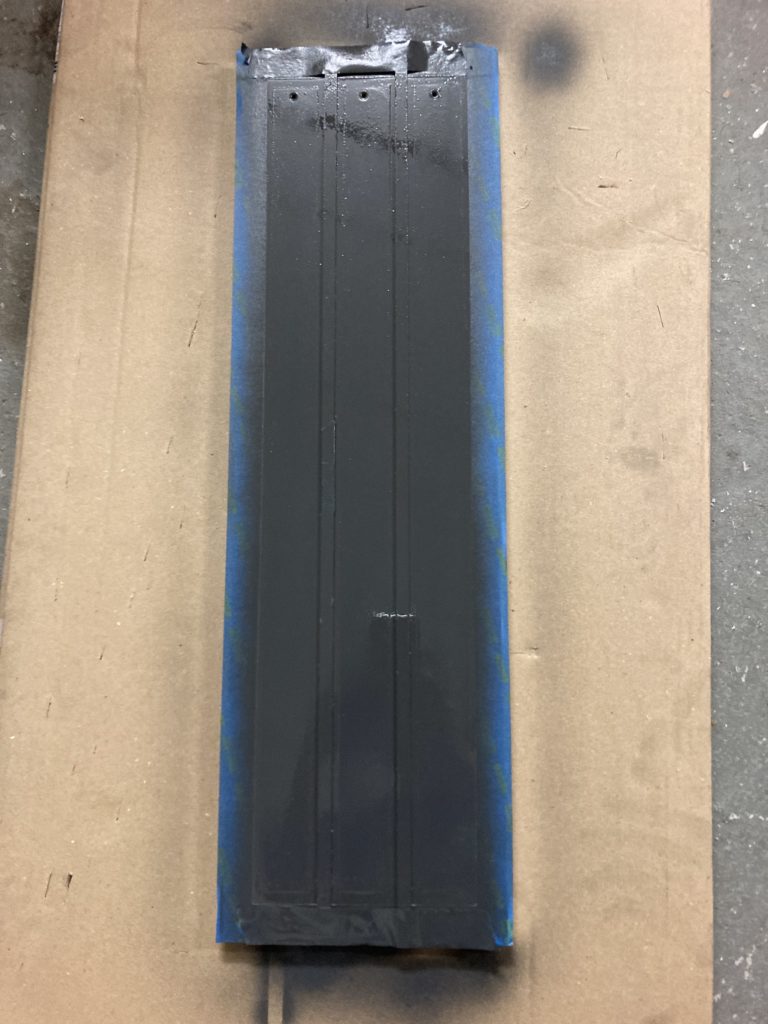
Note that several procedures are described here, since there were several trials: drill first then apply conductive paint second, or the opposite ? Thus, read the full page and make up your mind.
Notes/check list:
- Use rigid PVC 2mm and 0.5mm, “unplasticized”. Although for treble 2mm is a bit too much: see Baxandall
- Drill at 12500tr/min with quality bits. 1/8inch for holes, 4mm for screws
- if using mylar film, use annealing (heat under tension), or apply heating after glueing it
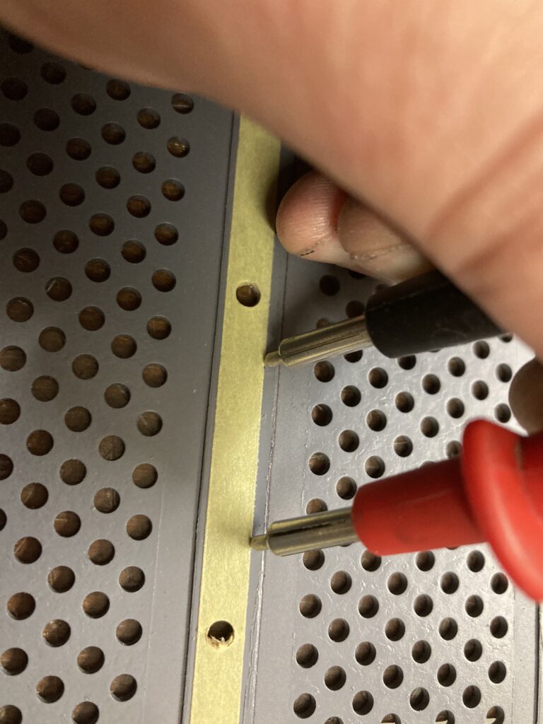
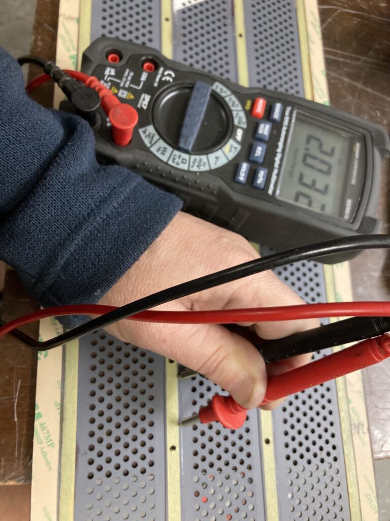
- Each stripe of conductive paint should measure around 30kOhm (use large probes). You can use Kontakt 35 (copper) or 33 (graphite). Several layers are required. If not conductive enough, you can first add a stripe of conductive tape on the outter side and puncture.
- Let the coating dry enough time to avoid sticking it to the stator
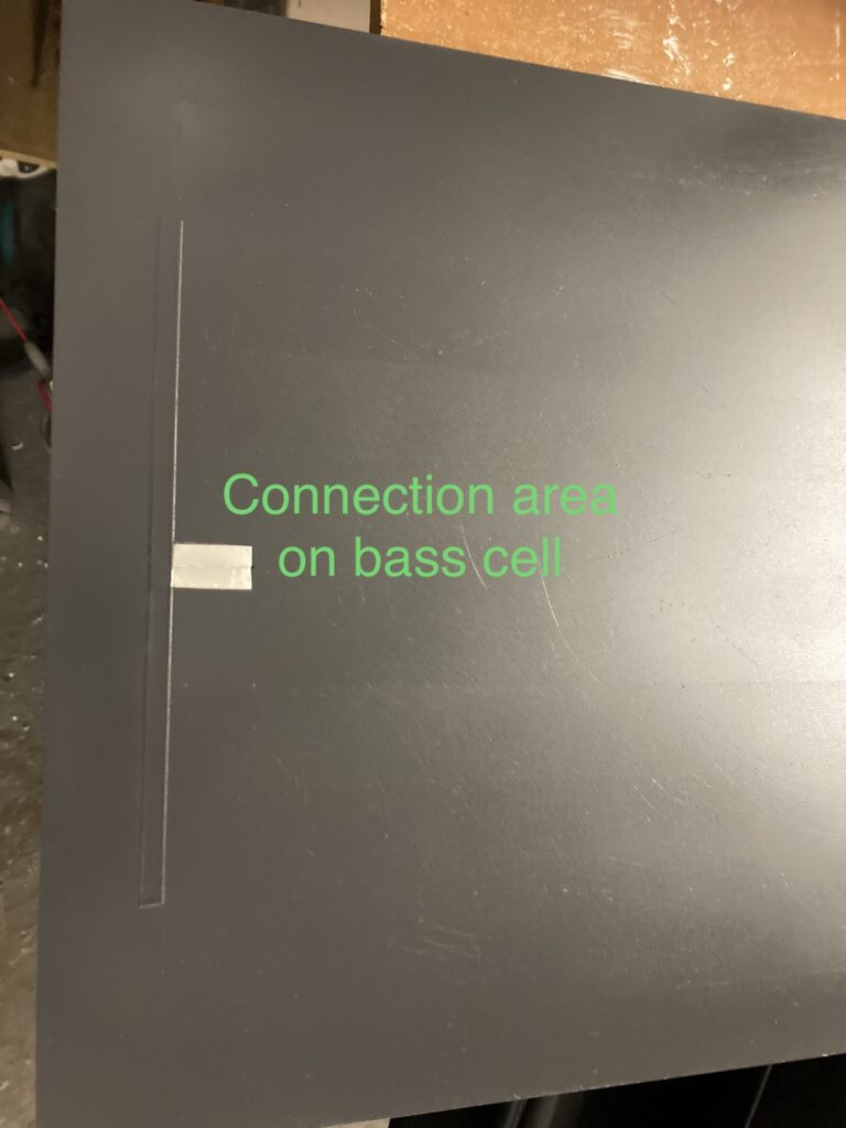
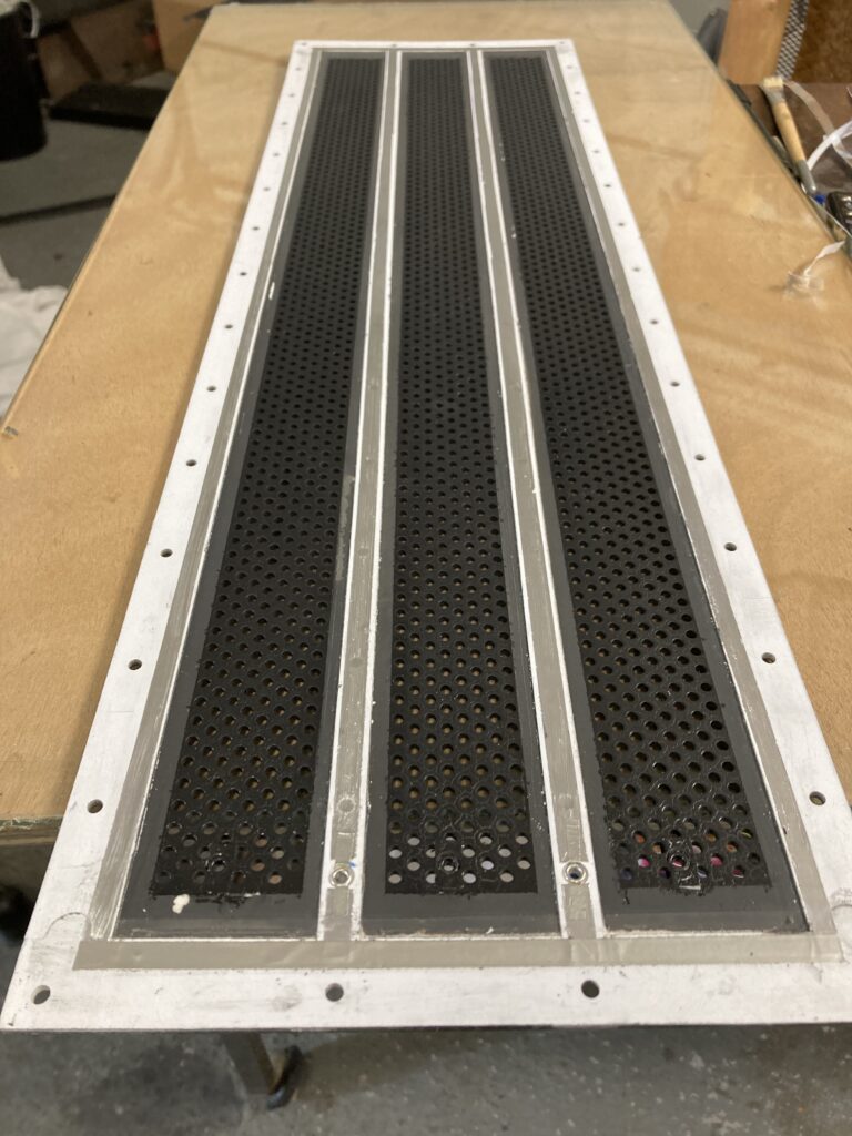
Notes for bass cells:
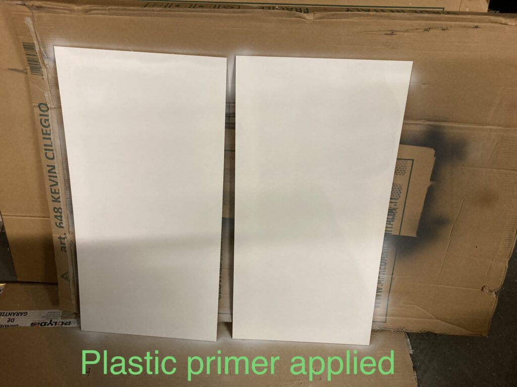
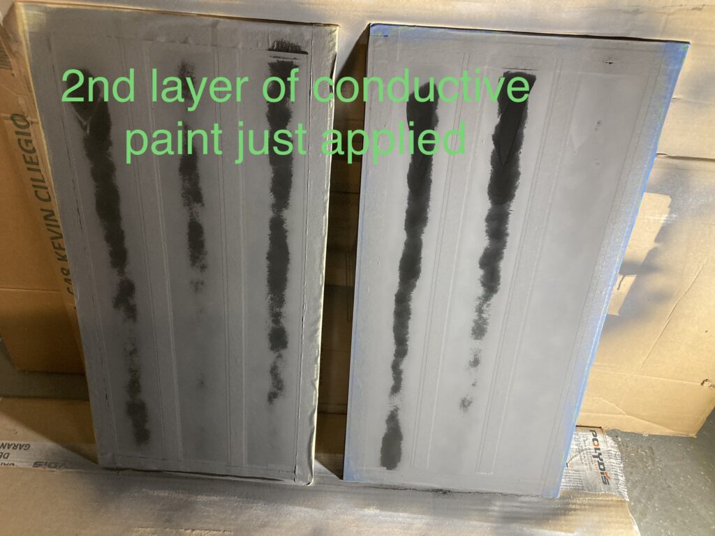
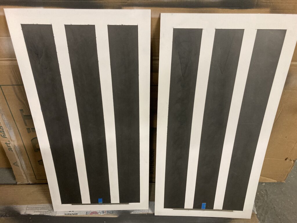
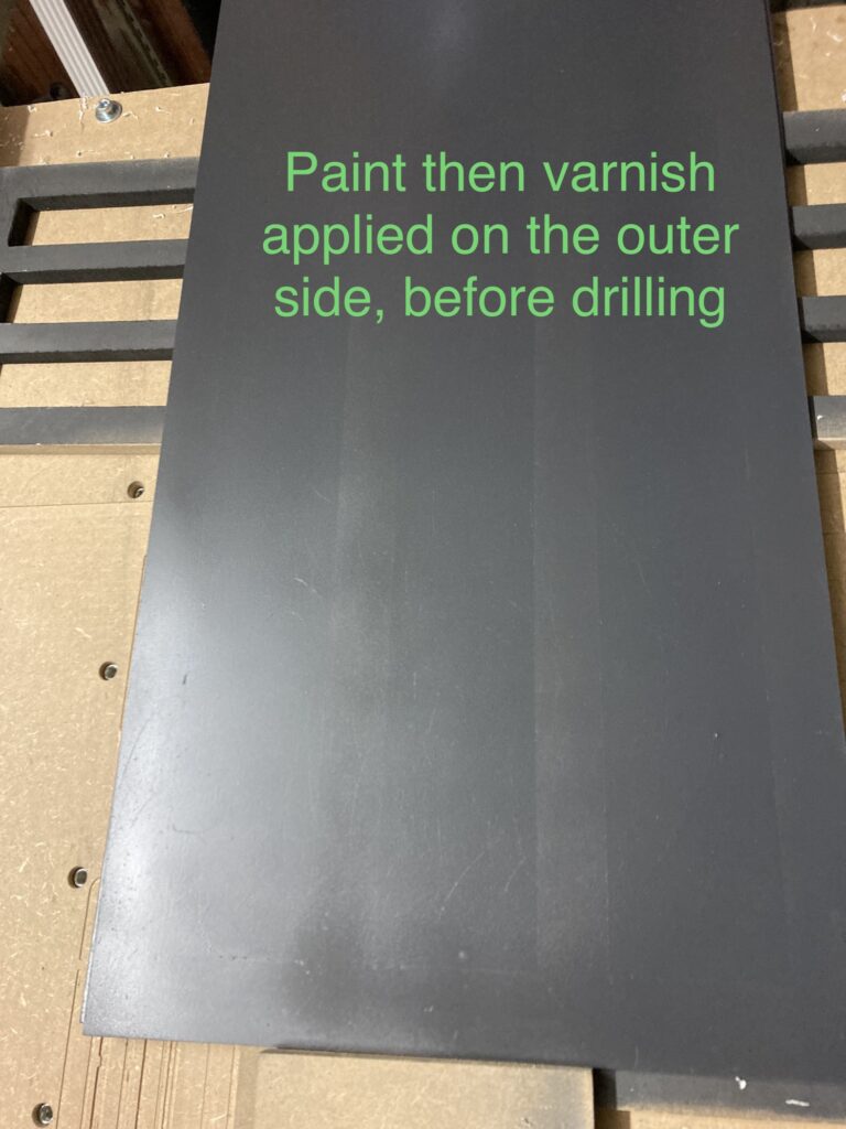
- Apply one layer of plastic primer, 2 layers or more of graphit 33, add the conductive tape (link between the 3 bands and connection area), 2 layers of paint (for bumpers), possibly varnish, then drill holes
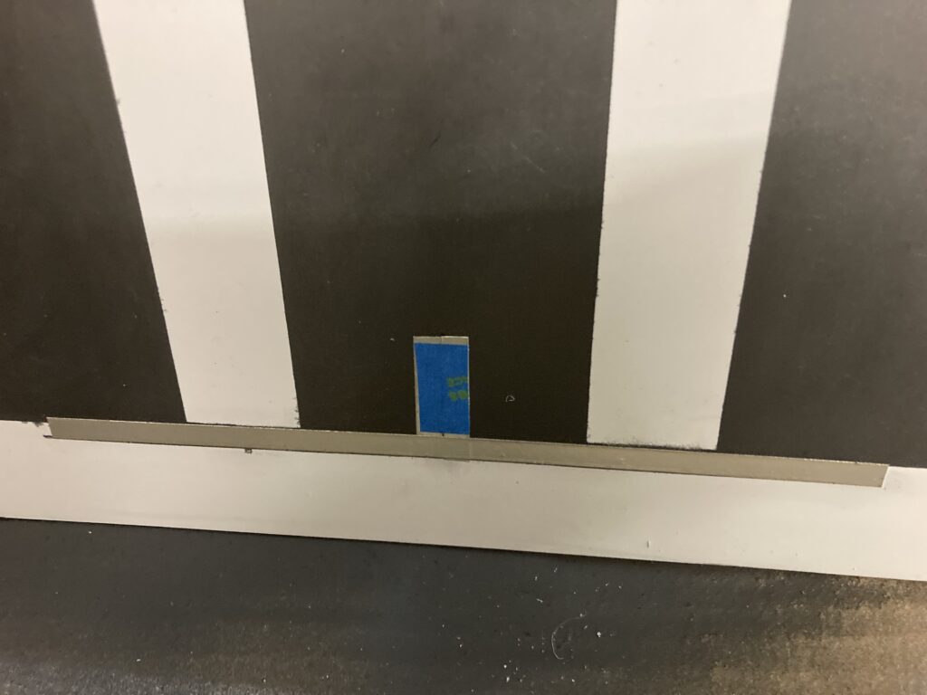
- install spacers (2 of them already painted with graphit), drill holes for screws and rivets. Enlarge those for rivets on inner side. Install conductive tape for polarization and rivets
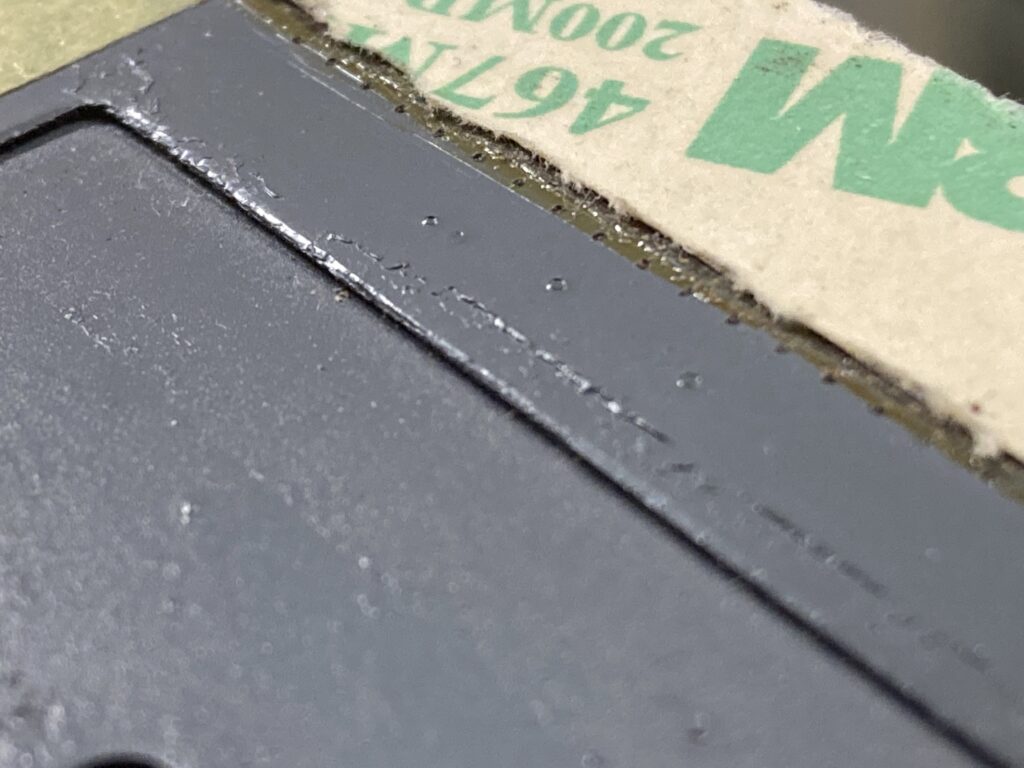
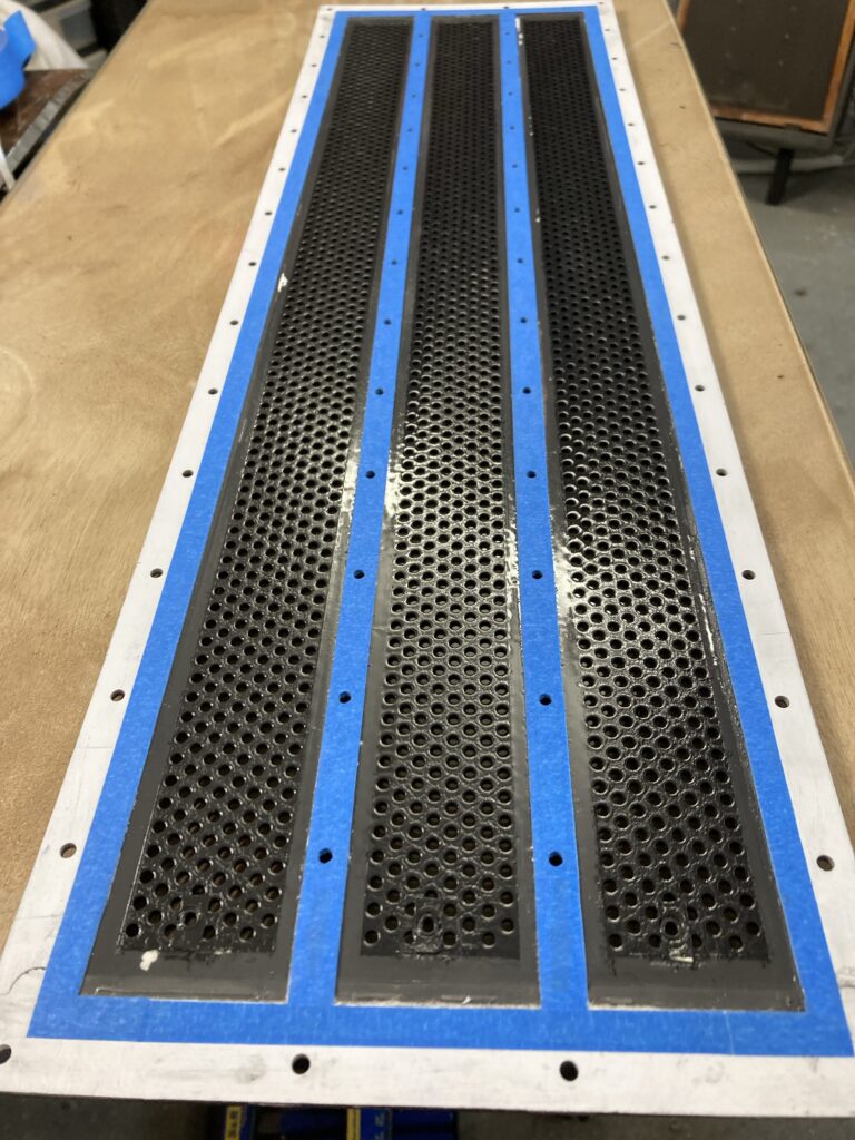
- For the 2 long external conductive stripes, use standard aluminium tape, and install them first. For all others, use 3M 1183
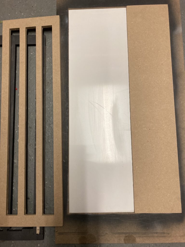
Notes for treble cells:
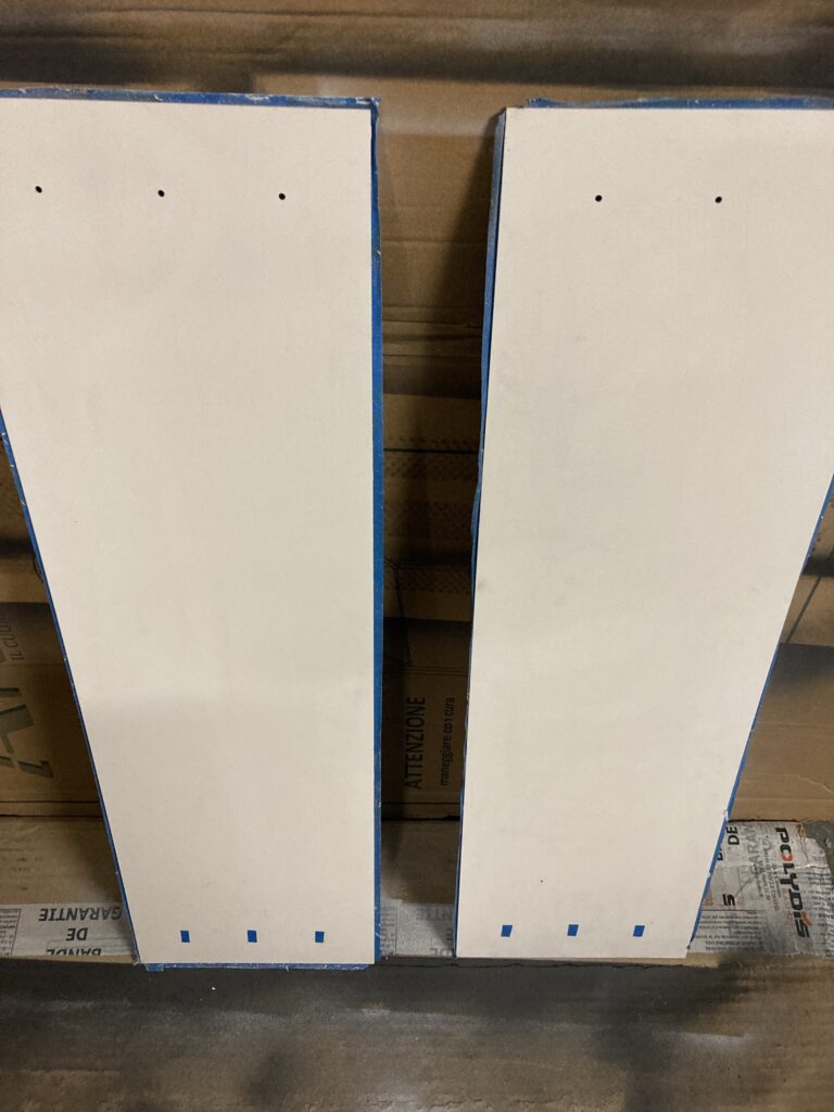
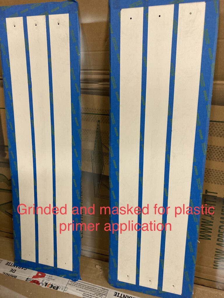
- Positions spacers to mark painting area
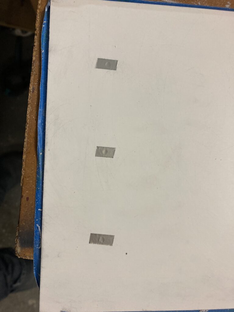
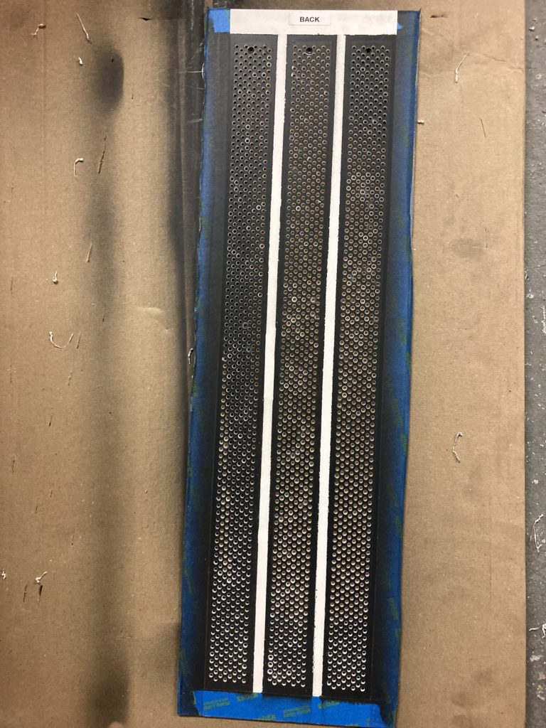
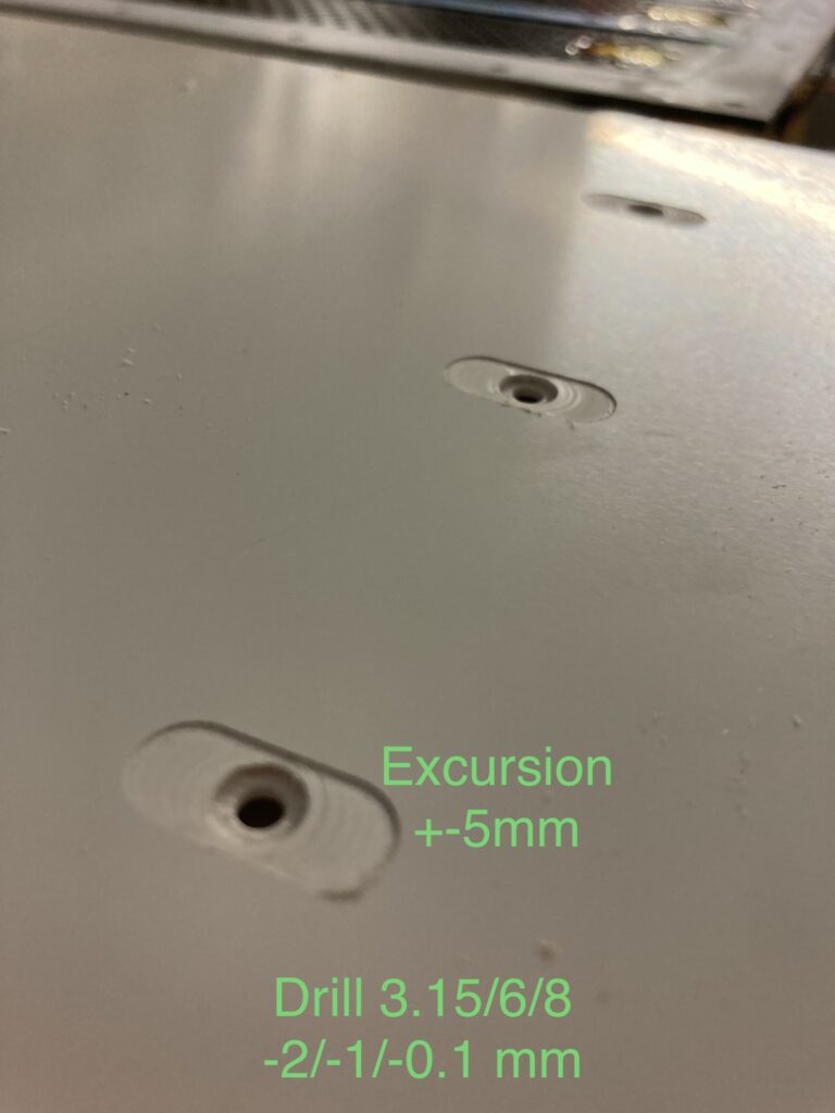
- Drill 3 holes in stators for connections and enlarge down to 1.0mm. You may do the same thing on the other side to check connectivity easily later. Drill a narrow path (depth 0.1mm) to add conductive tape
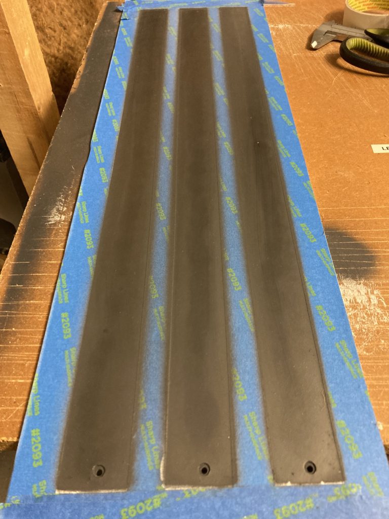
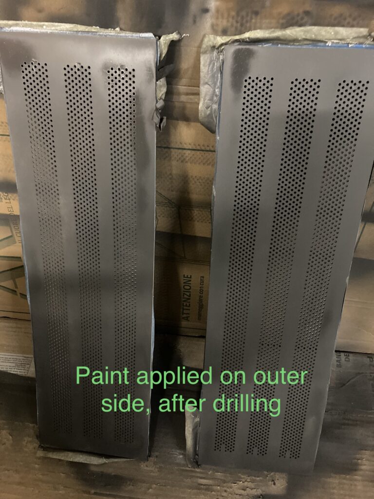
- Apply one layer of plastic primer, 2 layers or more of graphit 33, stripes of conductive tape, 1 layer of paint on both sides (except over the 3+3 holes), drill
- install spacers. Attention: see special chapter on polarisation. Indeed treble cells have a hidden conductive web
- Enlarge the 2 holes used for polarisation
- then second layer of paint (on both sides, still except over the 3+3 enlarged holes), then varnish KF 1282 (especially on internal side), install connectors and rivets used for polarisation
- Alternatively drill holes first then apply various layers of paint: make up your own mind !
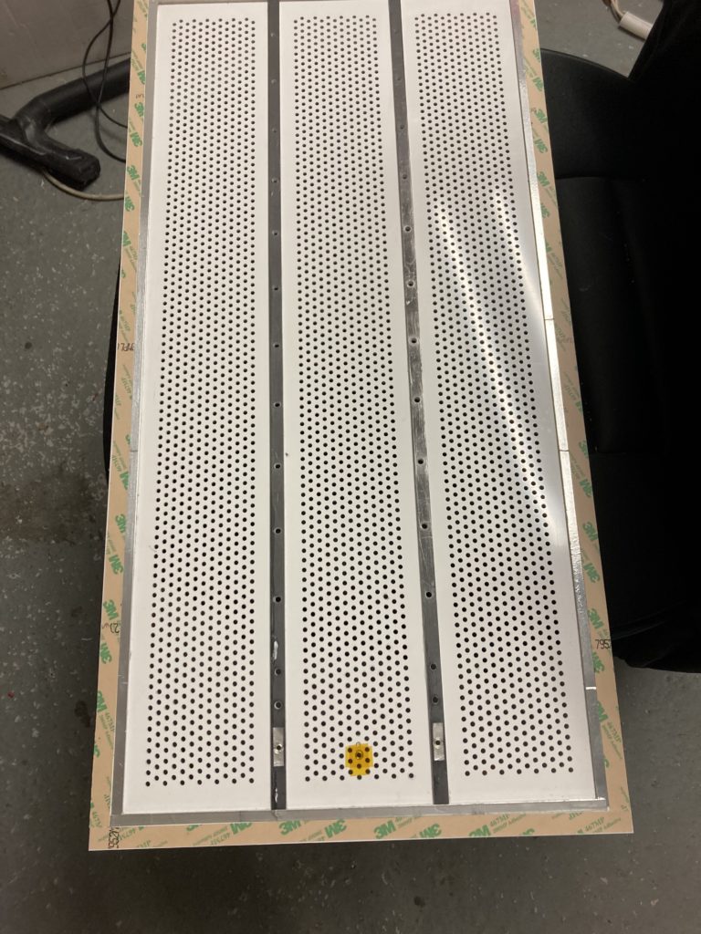
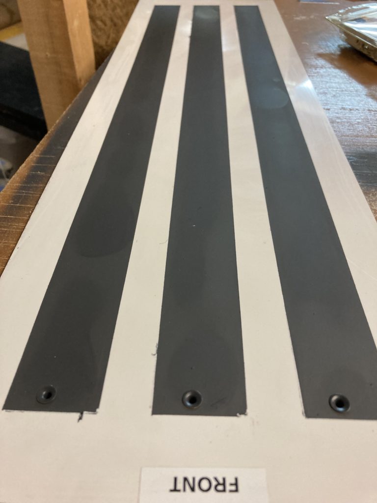
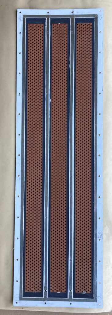
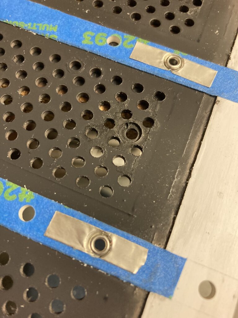
Illustration for alternative solution: drill first, apply conductive paint second:
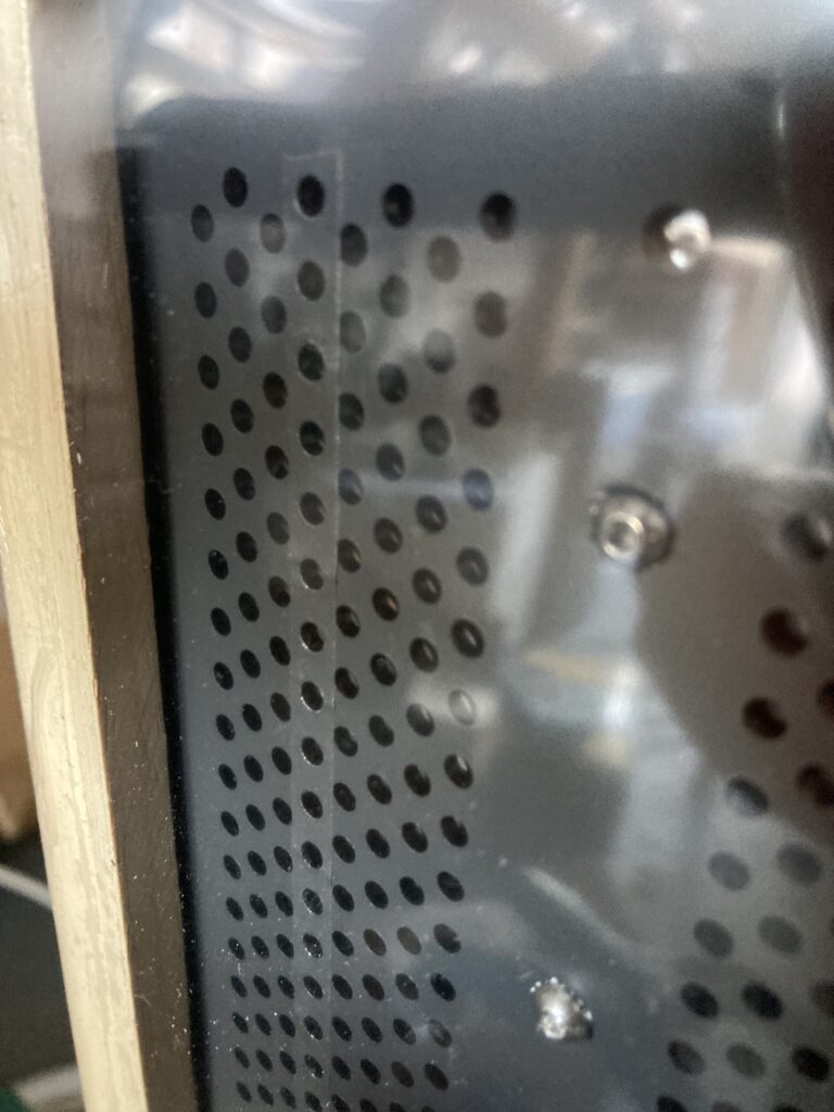
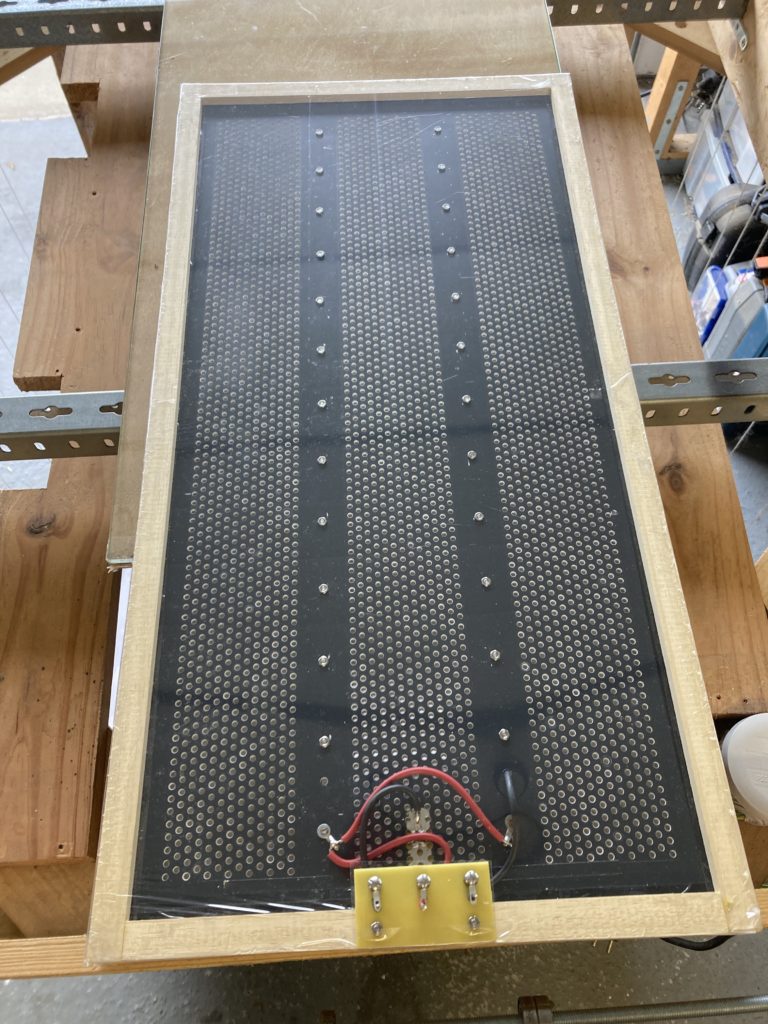
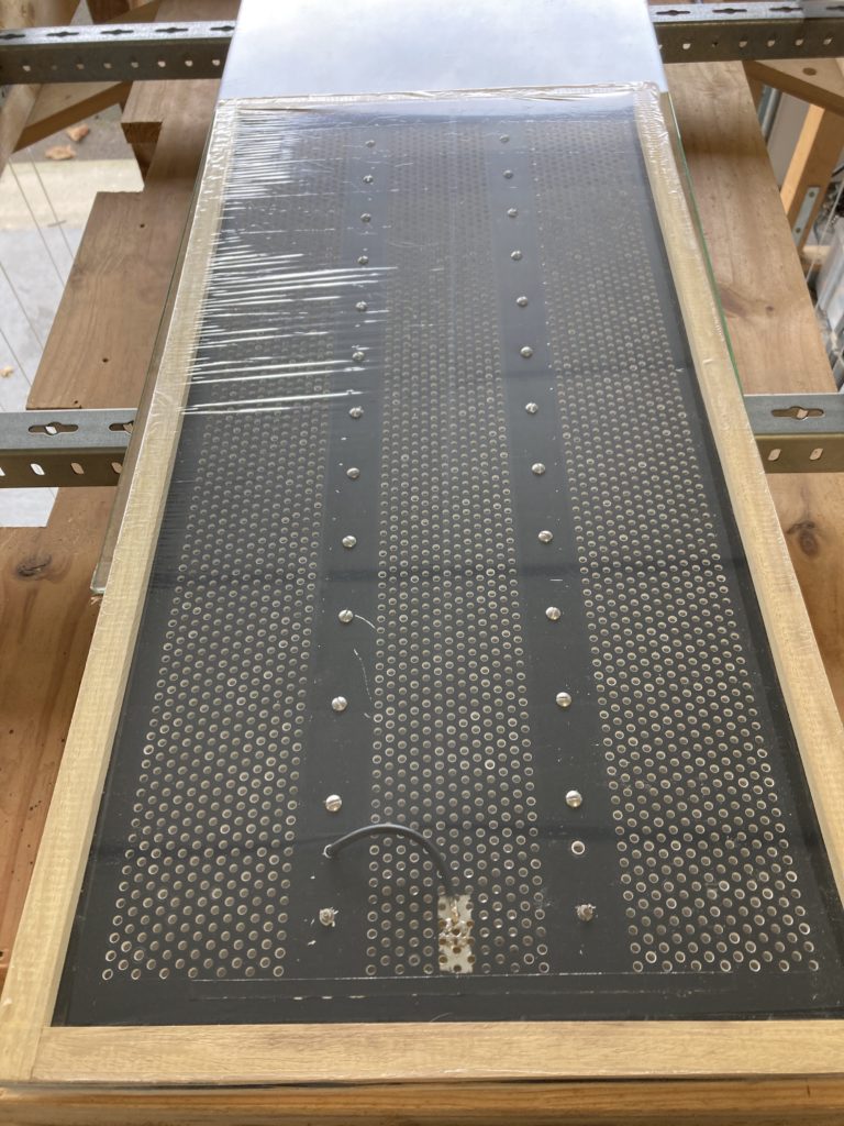
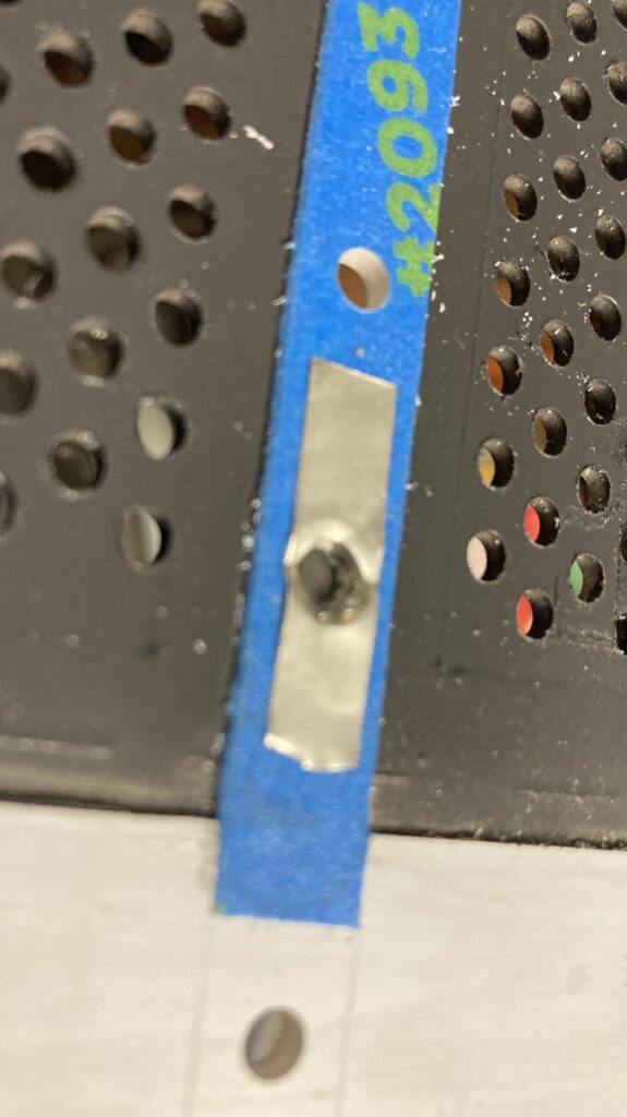
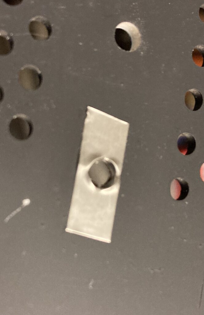
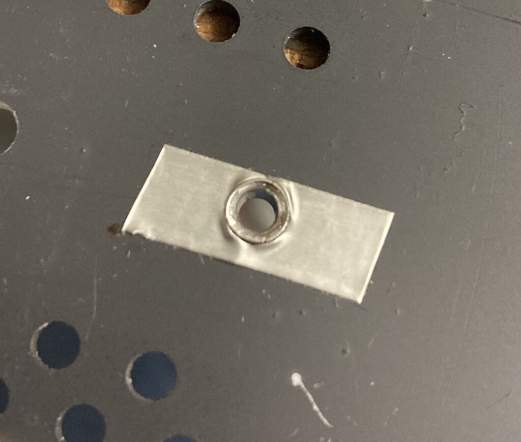
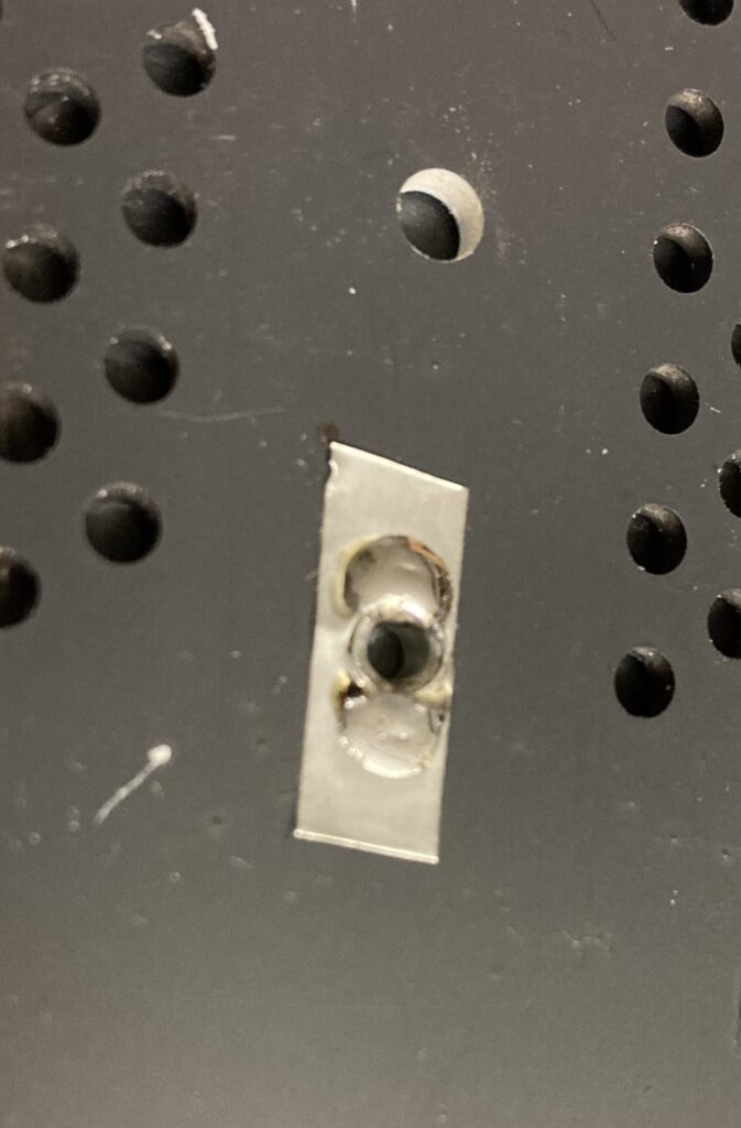
Install rivets for connectors and polarisation:
- Apply stripes of conductive tape 3M 1183, on both sides
- Puncture them (a cross with a cutter) then insert rivet from both sides
- fix rivet and solder it to the tape on the outer side
Open questions:
- paint bass dust cover or not ? All sources say this is cosmetic only. My theory: this adds weight and thus might filter somehow
- (…)
Treble cell polarisation web
This is a detail I noticed lately. There is a hidden layer of conductive paint below the paint, below the damping paper, on the spacers. Supply is tightly connected to this layer. Diaphragm of bass cells is directly connected to supply. For treble cell, this is indirect, and this is named capacitive charging.
![]()