Audio input transformer is a step-up kind with ratios of 90 for treble and 270 for bass (quote from quadesl.com). Sheldon Stokes says 96/270. diyAudio/bolserst says 87/290. diyAudio/Imazed says 96/289 … But this is based on voltage or turns measurement ? Probably first choice: voltage measurement.
You can read 55/110 here. This ratio is for windings themselves, and overall this makes 2*55 and (110+2*55+110): “110 / 330”. It may be related to turns ratio this time.
Maximum voltage at treble side should remain far below 3kV, which can be forced by an optional clipping board that clamps at 2200V. This 3kV corresponds to about 33Vp at input side.
Components used inside audio transformer do have to support up to 6kV. But this happens only with high power amplifiers such as Quad 303 (2x45W). With 5W, voltage inside audio transformer will stay below 100V. But who wants to use as little power as 5W with a low sensitivity speaker? Therefore, use high voltage components only! quadesl.org specifies 10kV for resistors and 4 to 6 kV for capacitors. Considering schematic (3 resistors inserted in serie in the bass line), VR37 are probably good enough. VR68 will be overkill but are still good choice since same size as original components. Besides, 1W vs 1/2W.
Model
An interesting discussion occured on diyAudio, here. See some extracts from contributor ‘bolserst‘ below:
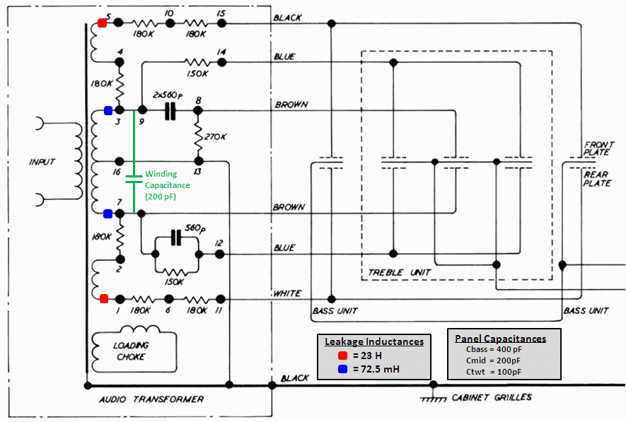
For a complete understanding of the ESL-57 crossover as well as its acoustic design I would highly recommend reading the description by Peter Baxandall on pages 169 – 179 of “Loudspeaker and Headphone Handbook”, J. Borwick, Ed. |
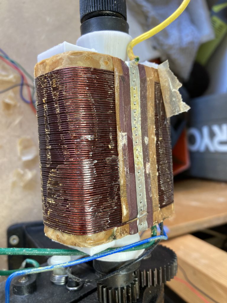
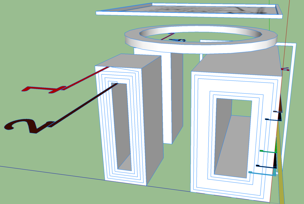
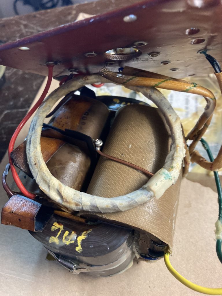
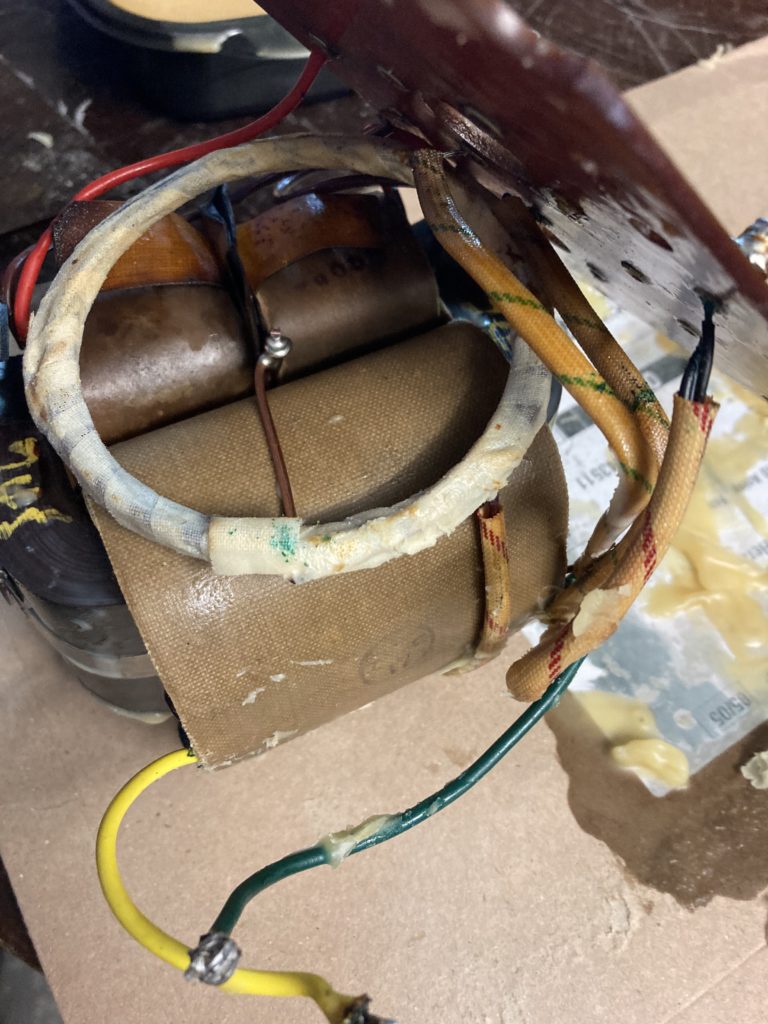
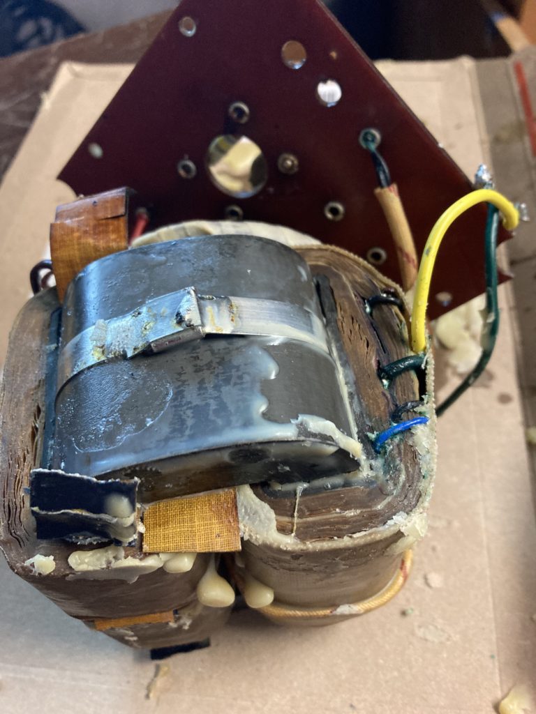
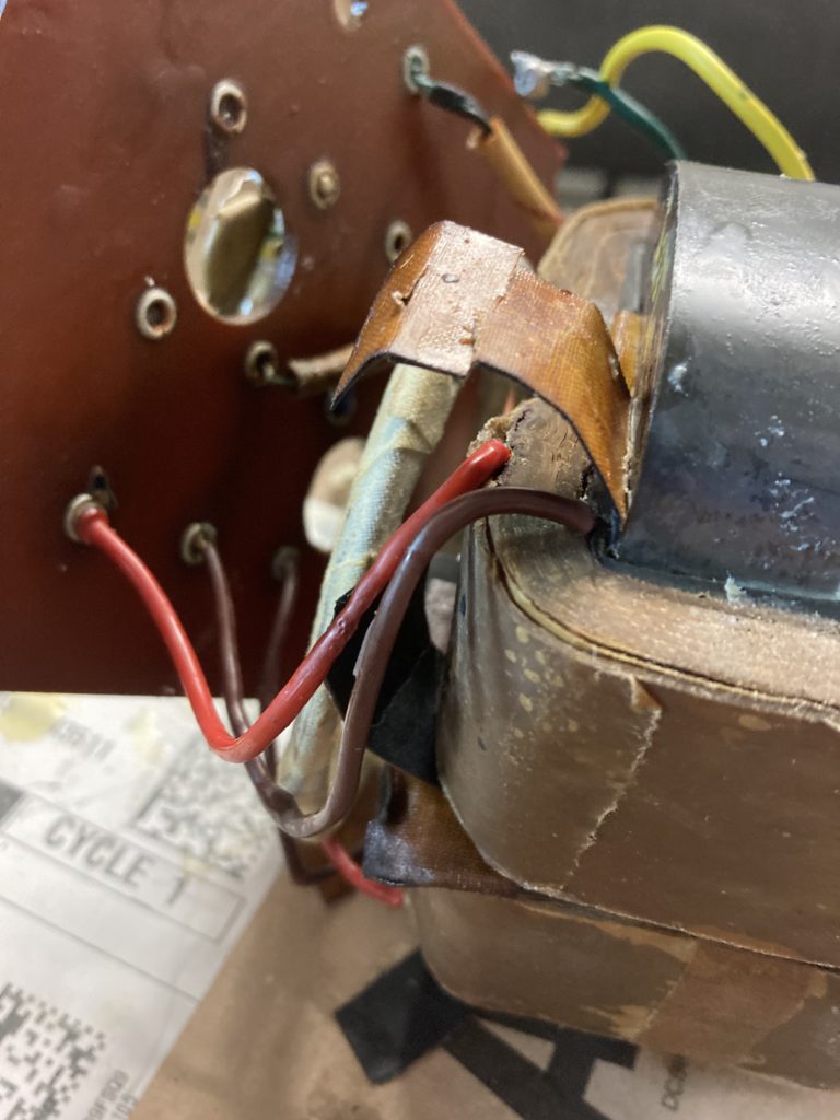
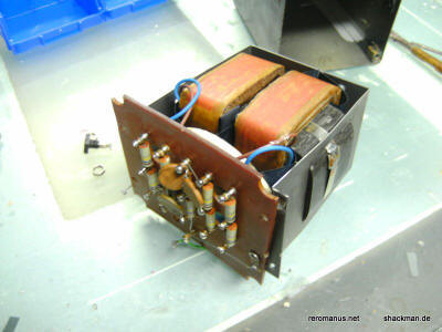
As you can see on pictures above:
- outer wires of the 2 small coils connect to outer terminals (1 and 5 for serie 2)
- inner wires of the 2 small coils connect to inner terminals (2 and 4 for serie 2)
- small coils are on the top side (near plots 1 .. 5) and are a priori identical
How many turns ? I got this from one source:
- Small coils are expected 7850 turns gauge #39 (0.0889mm) !! not what I measured, see below !!
- Audio inputs (B/R) make 74 turns, gauge #21 (0.7239mm)
- Last, big coils, 2 times 3926 turns gauge #39, turns ratio 53
On my side, I measured for small coils:
- for one transfo, 180 turns per layer (width = 1 inch, thus diameter<0.141mm), and computed 1715 Ω/km: gauge #37 (0.113mm)
- for another transfo, I got this on just one layer (slightly less accurate): 34.7m for layer #4 and 64.7Ohm and 3.1g -> 1.86Ohm/m, 89g/km: definitely gauge #37
- for one coil, 41 layers, first and last being partly filled, around 180 turns/layer, 180*40.5=7290 turns in total
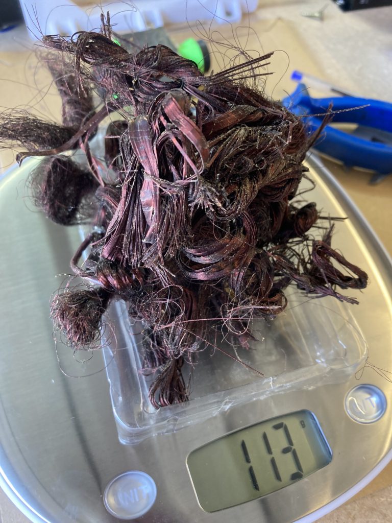
- for another coil, 40 layers only, around 182.5 turns/layer, 128 only for first and last, 7211 turns in total, 113g of wire
- this makes turns ratio 97.5 .. 98.5, resistance close to 2.2 kΩ. Obviously only total number of turns was monitored
For big coils, and each instance of high voltage wiring:
- 8 layers, first and last being half filled
- 565 turns per complete layer: about 3955 turns in total (turns ratio 53)
- target is 1.93/1.73 kΩ (note that inner and outer wiring have same # of turns but not same radius thus not the same resistance)
For big coils, low voltage wiring:
- I confirm gauge 21, 74 turns, 0.58 Ohm, 13.25m, 1 layer only
Additional notes:
- 1st layer is half-filled, and starts towards left
- seen from connection wires, small and big coils are NOT wired in the same sense: anti-clockwise for small ones
- 3.5 turns of paper is used between layers for insulation of big coils, only 1.5 turns for small coils
- big coils have additional external insulation layers (4m30!), less for small coils (1m)
- not all coils measure the same !
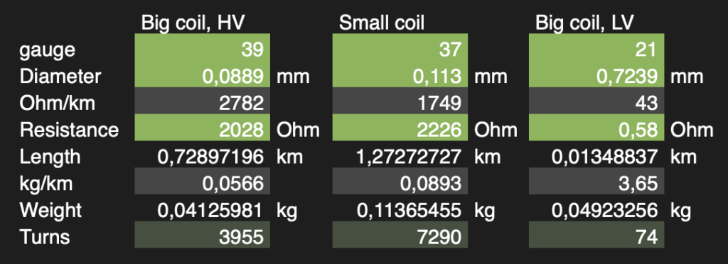
My summary:
- apply turns ratio of 53/98 (this makes a voltage ratio of “106/302” before applying yield and loss, to obtain hopefully the famous “90/290” after)
- small coils: layers of 180 .. 185 turns, gauge 37, 40 .. 41 layers, 7250 turns (first and last layers filled at 75%), set winding tool with a spacing for a gauge 2 steps below (25.4mm/180). 1.5 turn of insulation between each layer (1.5 inch), 5 turns for final insulation
- big coils, HV: layers of 565 turns, gauge 39, 8 layers, 3950 turns (first and last half-filled)
- big coils, LV: 1 layer of 74 turns gauge 21
- once completed with external insulation, small coils should mesure less than 42x76mm (paper core is 21x56mm, height 36mm, external side). One turn will vary between 19.3cm and 15.4cm (avg 17.35cm thus roughly 1265m in total and 2.2kOhm)
- for big coils, height of paper core is 74mm (insulation can be 2×1.5 inches wide)
- the 2 small coils are identical. Take care to wire direction: see picture
Impedance computation:
- http://www.dicks-website.eu/coilcalculator/
- https://www.eeweb.com/tools/rectangle-loop-inductance/
- https://www.diyaudio.com/community/threads/explaining-the-quad-esl-57-crossover.224615/
- big coil, LV, 100mH (Al value = 18260nH/N^2)
- big coil, HV, 300H
- small coil, 1000H
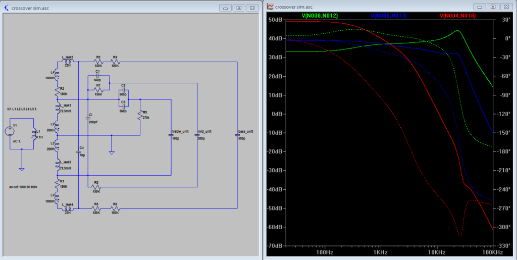
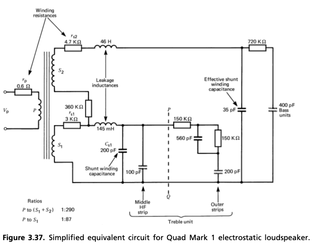
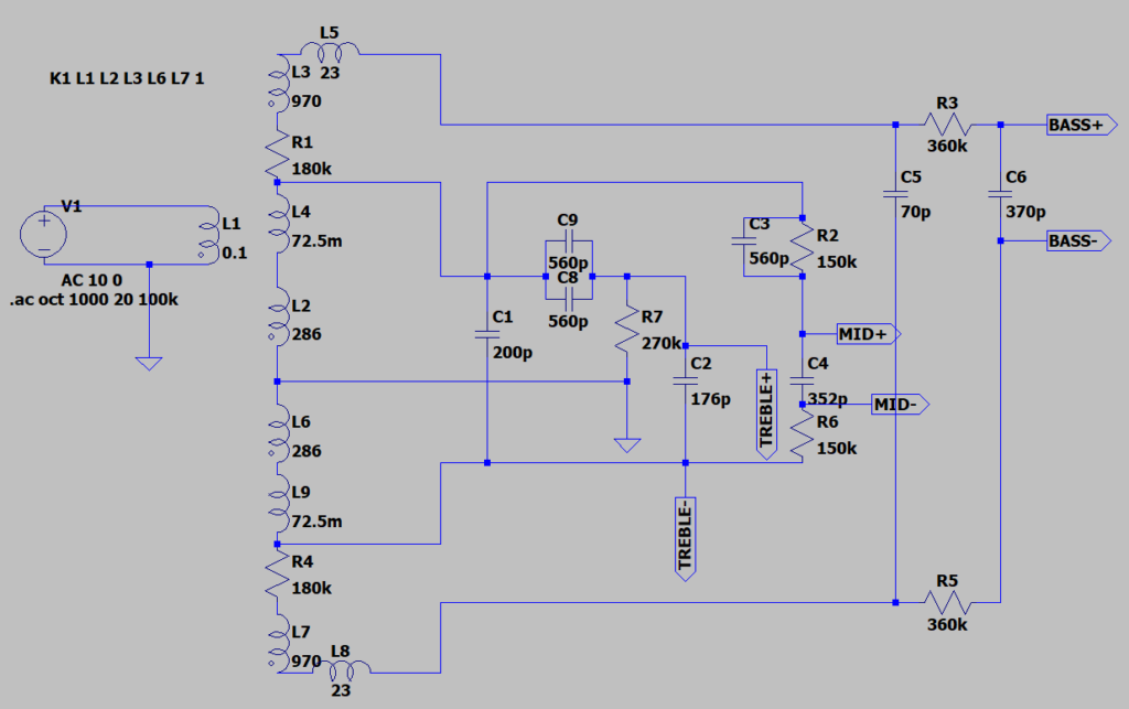
Here is a code to reproduce measurements above, with figures from Baxandall:
Version 4.1
SHEET 1 1196 760
WIRE 32 -128 0 -128
WIRE 224 -128 112 -128
WIRE 0 -32 0 -48
WIRE 224 -32 224 -128
WIRE 848 -32 224 -32
WIRE 880 -32 848 -32
WIRE 992 -32 960 -32
WIRE 1056 -32 992 -32
WIRE 848 32 848 -32
WIRE 992 32 992 -32
WIRE 224 48 0 48
WIRE 720 48 288 48
WIRE 0 64 0 48
WIRE -96 80 -320 80
WIRE 720 96 720 48
WIRE 720 96 640 96
WIRE 992 128 992 96
WIRE 1056 128 992 128
WIRE -176 160 -320 160
WIRE -96 160 -176 160
WIRE 224 176 224 48
WIRE 288 176 288 48
WIRE 288 176 224 176
WIRE 368 176 368 128
WIRE 368 176 288 176
WIRE 432 176 432 128
WIRE 480 176 432 176
WIRE 560 176 480 176
WIRE 640 176 640 160
WIRE 720 176 640 176
WIRE 0 192 0 144
WIRE 368 208 368 176
WIRE 432 208 432 176
WIRE 480 208 480 176
WIRE 288 224 288 176
WIRE 720 256 720 176
WIRE 768 256 720 256
WIRE 560 272 560 176
WIRE 672 272 560 272
WIRE -176 288 -176 160
WIRE 560 288 560 272
WIRE 720 288 720 256
WIRE 672 304 672 272
WIRE 0 320 0 272
WIRE 480 320 480 288
WIRE 480 320 0 320
WIRE 0 352 0 320
WIRE 816 352 720 352
WIRE 480 400 480 320
WIRE 288 432 288 288
WIRE 288 432 224 432
WIRE 560 432 560 352
WIRE 560 432 288 432
WIRE 720 432 560 432
WIRE 0 448 0 432
WIRE 560 480 560 432
WIRE 0 544 0 528
WIRE 224 544 224 432
WIRE 224 544 0 544
WIRE 848 624 848 96
WIRE 848 624 224 624
WIRE 880 624 848 624
WIRE 992 624 992 128
WIRE 992 624 960 624
WIRE 0 640 0 624
WIRE 48 720 0 720
WIRE 224 720 224 624
WIRE 224 720 128 720
FLAG -176 288 0
FLAG 1056 -32 BASS+
IOPIN 1056 -32 Out
FLAG 480 400 0
FLAG 672 304 TREBLE+
IOPIN 672 304 Out
FLAG 768 256 MID+
IOPIN 768 256 Out
FLAG 1056 128 BASS-
IOPIN 1056 128 Out
FLAG 560 480 TREBLE-
IOPIN 560 480 Out
FLAG 816 352 MID-
IOPIN 816 352 Out
SYMBOL ind2 -112 64 R0
SYMATTR InstName L1
SYMATTR Value 0.1
SYMATTR Type ind
SYMATTR SpiceLine Rser=0.6
SYMBOL ind2 -16 176 R0
SYMATTR InstName L2
SYMATTR Value 286
SYMATTR Type ind
SYMATTR SpiceLine Rser=2028
SYMBOL ind2 -16 -144 R0
SYMATTR InstName L3
SYMATTR Value 970
SYMATTR Type ind
SYMATTR SpiceLine Rser=2226
SYMBOL res -16 -48 R0
SYMATTR InstName R1
SYMATTR Value 180k
SYMBOL ind -16 48 R0
SYMATTR InstName L4
SYMATTR Value 72.5m
SYMATTR SpiceLine Rser=1m
SYMBOL ind 16 -112 R270
WINDOW 0 32 56 VTop 2
WINDOW 3 5 56 VBottom 2
SYMATTR InstName L5
SYMATTR Value 23
SYMBOL cap 272 224 R0
SYMATTR InstName C1
SYMATTR Value 200p
SYMBOL cap 544 288 R0
SYMATTR InstName C2
SYMATTR Value 176p
SYMBOL cap 624 96 R0
SYMATTR InstName C3
SYMATTR Value 560p
SYMBOL cap 832 32 R0
SYMATTR InstName C5
SYMATTR Value 70p
SYMBOL cap 976 32 R0
SYMATTR InstName C6
SYMATTR Value 370p
SYMBOL res 704 80 R0
SYMATTR InstName R2
SYMATTR Value 150k
SYMBOL res 976 -48 R90
WINDOW 0 0 56 VBottom 2
WINDOW 3 32 56 VTop 2
SYMATTR InstName R3
SYMATTR Value 360k
SYMBOL voltage -320 64 R0
WINDOW 3 24 96 Invisible 2
WINDOW 123 24 118 Left 2
WINDOW 39 0 0 Left 0
SYMATTR Value ""
SYMATTR Value2 AC 10 0
SYMATTR InstName V1
SYMBOL ind2 -16 336 R0
SYMATTR InstName L6
SYMATTR Value 286
SYMATTR Type ind
SYMATTR SpiceLine Rser=2028
SYMBOL res -16 528 R0
SYMATTR InstName R4
SYMATTR Value 180k
SYMBOL ind2 -16 624 R0
SYMATTR InstName L7
SYMATTR Value 970
SYMATTR Type ind
SYMATTR SpiceLine Rser=2226
SYMBOL ind 32 736 R270
WINDOW 0 32 56 VTop 2
WINDOW 3 5 56 VBottom 2
SYMATTR InstName L8
SYMATTR Value 23
SYMBOL cap 704 288 R0
SYMATTR InstName C4
SYMATTR Value 352p
SYMBOL ind -16 432 R0
SYMATTR InstName L9
SYMATTR Value 72.5m
SYMATTR SpiceLine Rser=1m
SYMBOL res 976 608 R90
WINDOW 0 0 56 VBottom 2
WINDOW 3 32 56 VTop 2
SYMATTR InstName R5
SYMATTR Value 360k
SYMBOL res 704 336 R0
SYMATTR InstName R6
SYMATTR Value 150k
SYMBOL res 464 192 R0
SYMATTR InstName R7
SYMATTR Value 270k
SYMBOL cap 432 192 R90
WINDOW 0 0 32 VBottom 2
WINDOW 3 32 32 VTop 2
SYMATTR InstName C8
SYMATTR Value 560p
SYMBOL cap 432 112 R90
WINDOW 0 0 32 VBottom 2
WINDOW 3 32 32 VTop 2
SYMATTR InstName C9
SYMATTR Value 560p
TEXT -312 -96 Left 2 !K1 L1 L2 L3 L6 L7 1
TEXT -368 208 Left 2 !.ac oct 1000 20 100k
Pictures imported from other sites:
![]()