First of all, identify serie 1 or 2. Serie 2 started at serial number 16800 and adds filtering, which is essential to use the ESL with a Quad 303 or any other audio amplifier featuring more than 15W.
Fortunately, one can upgrade easily from serie 1 to serie 2, as shown below (pictures come from another site).
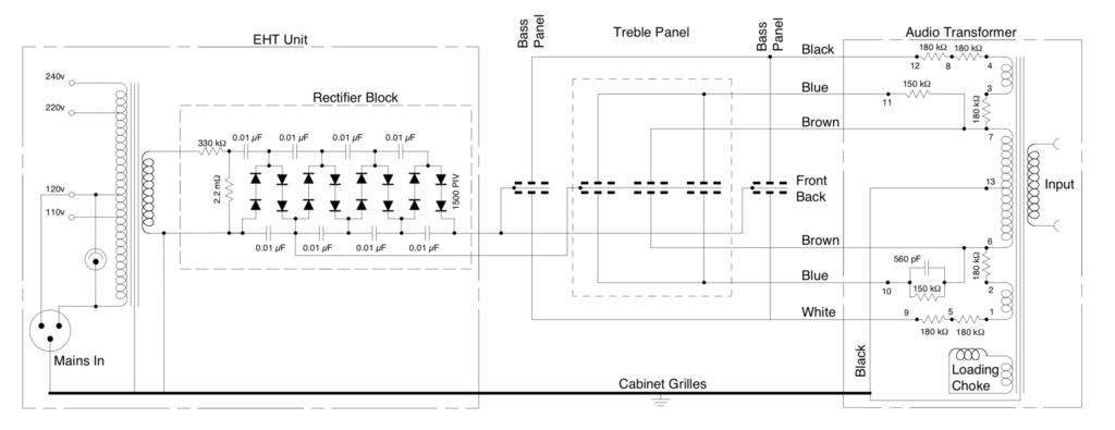
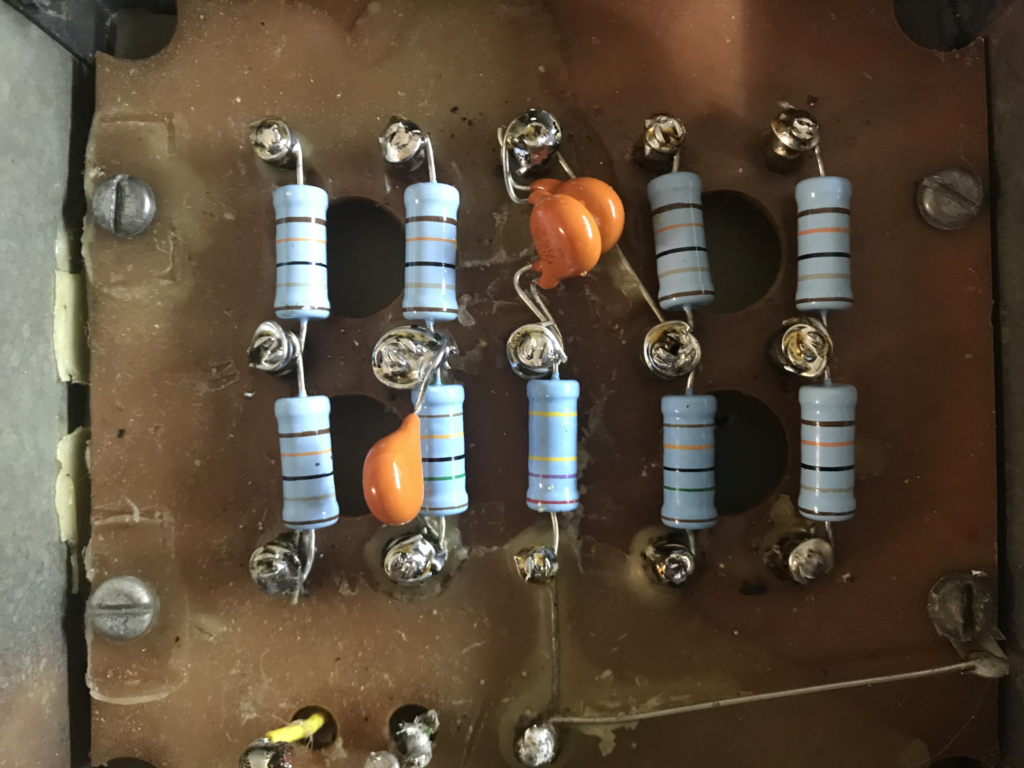
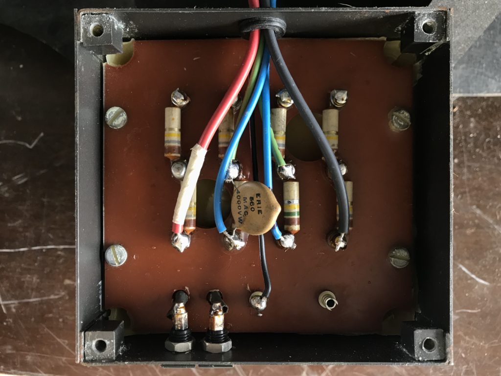
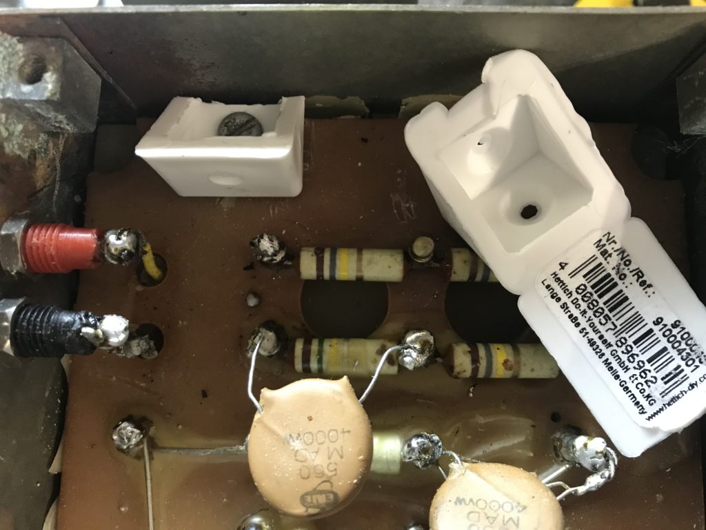
Serie 1 displays 4 columns of resistors. Pin numbering is 1 2 3 4 for 1st row, 5 6 7 8 for 2nd, 9 10 11 12 for 3rd, and 13 for the last isolated one at the very bottom.
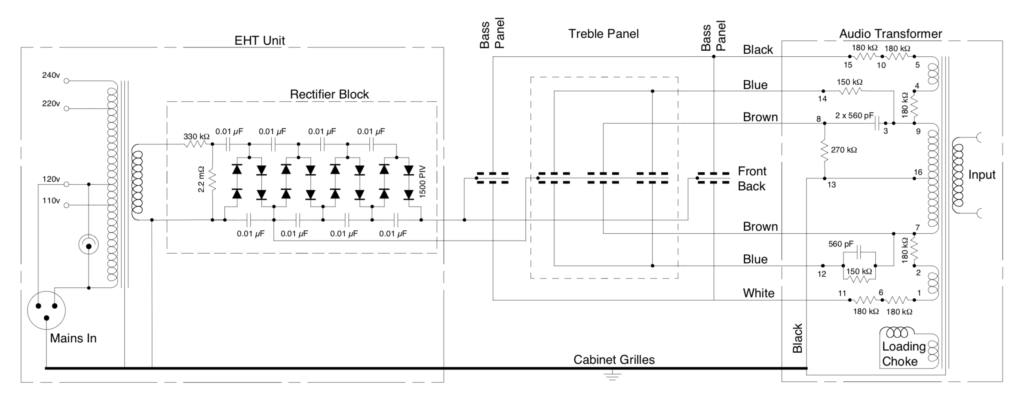
Serie 2 displays 5 columns of resistors. Pin numbering is natural as well, and visible on drawing.
If you unsolder the audio transformer, check windings and resistors using following schematics (from quadesl.com):
Tip: if you want to replace resistors, cut previous ones. Do not try to unsolder them.
Protect panels from arcing: concept
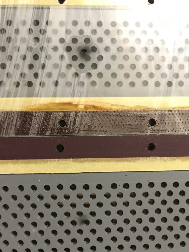
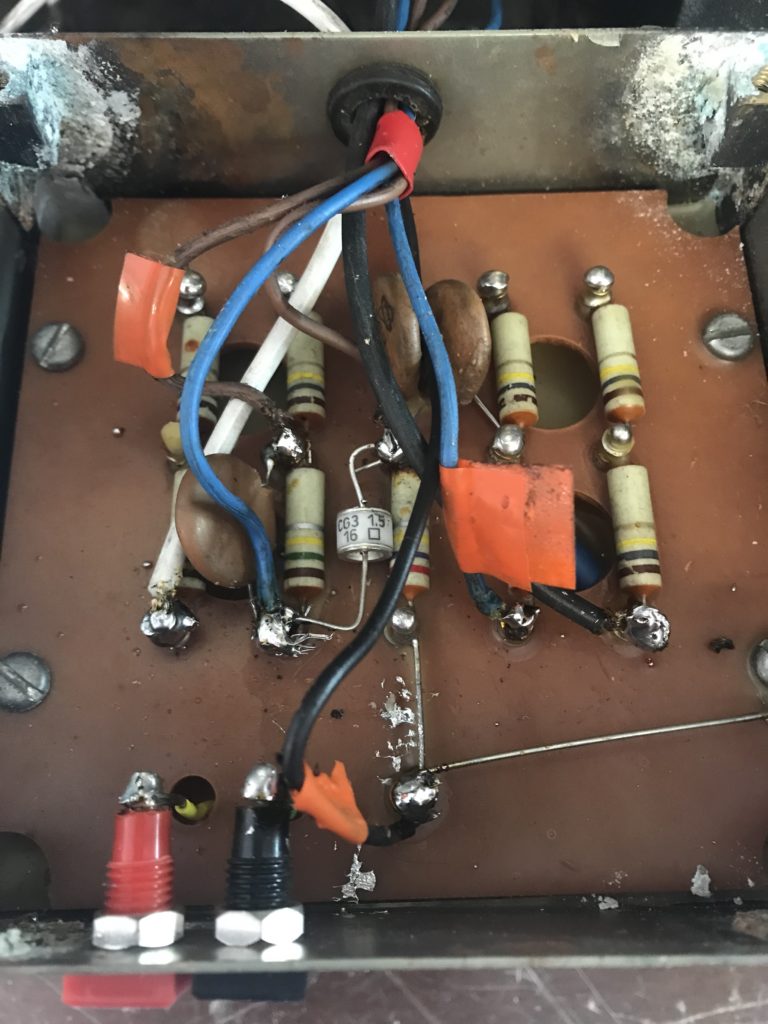
Arcing occurs on treble panel while overdriving the speaker. Too much voltage creates a short circuit between diaphragm and stators. If you drive the ESL (v2) with a Quad II or 303 or 405 (R11 installed) then no need for protection. Otherwise, this can happen:
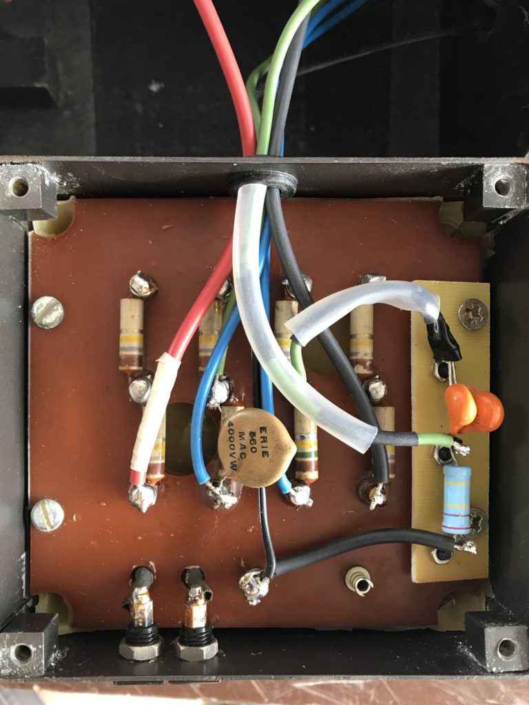
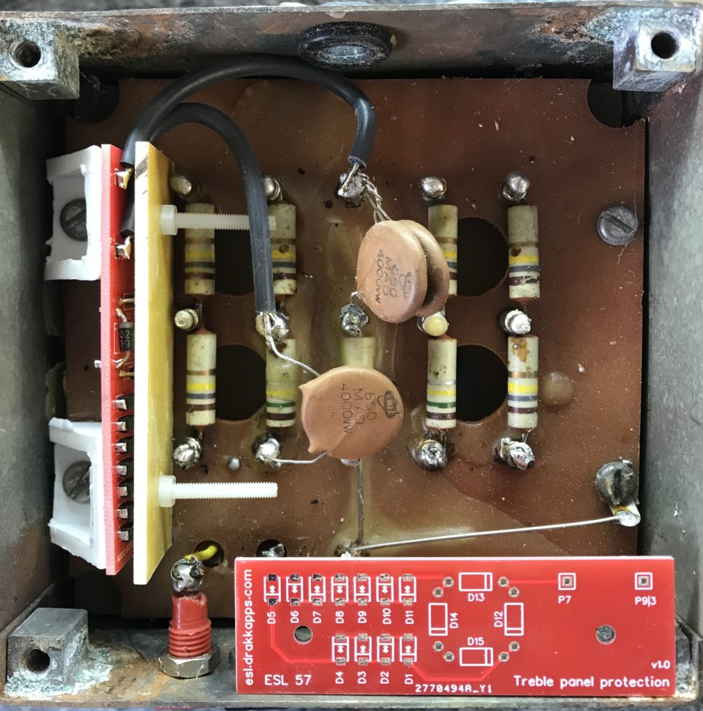
There are some options to protect panels from arcing. You will find details at quadesl.com. Concept is to clip to 2200V audio signal if using zener diodes (10 times 220V or 11 times 200V), or 1500V if using gas discharge tube (like CP Clare CG3-1.5L). Additional board is to be soldered between 6 and 7 (serie 1) or 7 and 9 (serie 2). Note for serie 2: “9” and “3” are equivalent if this can help soldering.
Note that on one hand quadesl.com indicates that arcing occurs between 3 and 3.3kV then on the other hand that Quad suggests clipping at 2200V. Thus why not a CG3-2.0L ? Might be that only impulse breakdown voltage is the one to consider ?
Question is now of no interest: quadesl.com does not suggest any more the gaz discharge tube:
“Original Quad ESL Treble Protection BoardsMonday, November 06th, 2017 | Author: stokes For a number of years, I suggested a gas discharge tube to protect the original Quad ESL treble panels. and they do work well, but I’ve had them get leaky over time and their striking voltage drops. I have reverted to the stock Quad ESL treble protection circuit. The original circuit is a rectifier bridge of 3000 volt diodes, where the input to the treble panel is applied across the AC inputs of the bridge. A stack of zener diodes is placed across the rectified outputs.”
Thus, no choice: go for the zener diode solution. This will clamp HV signal going to treble panel to 2200V, which makes margin compared to the well known “33Vp at input max” which makes 33*90=2970V at panel side.
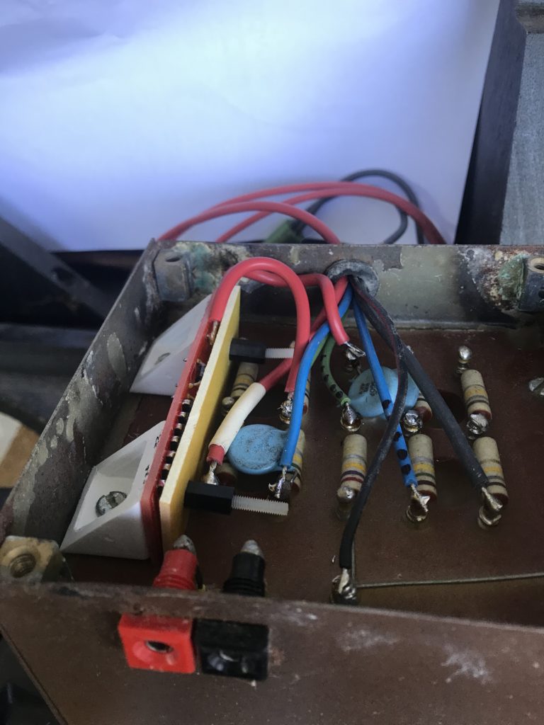
In all cases, don’t do that:
Upgrade audio transformer: how to
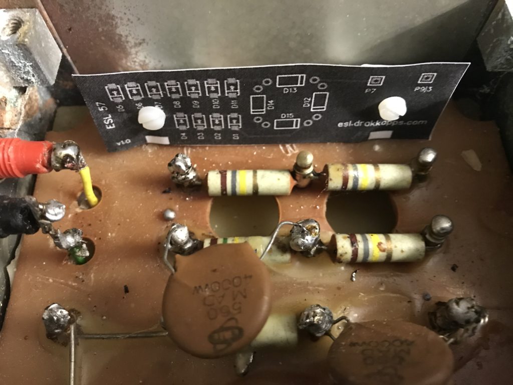
Upgrade audio transformer from v1 to v2 version. A custom board will be designed for this:
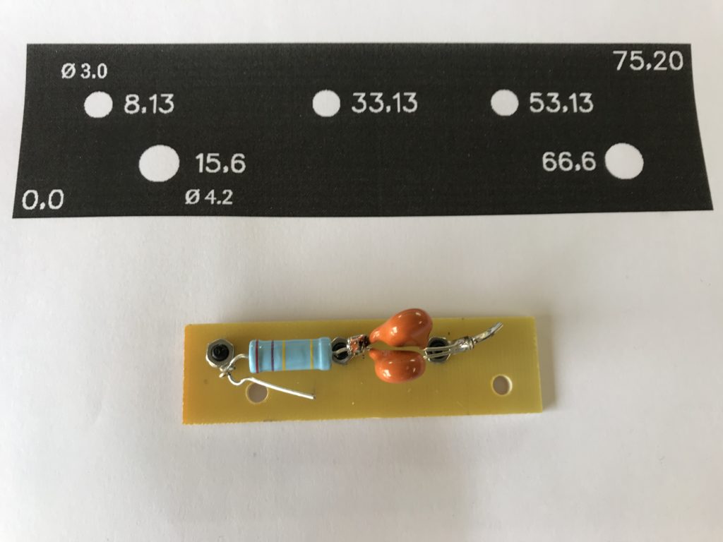
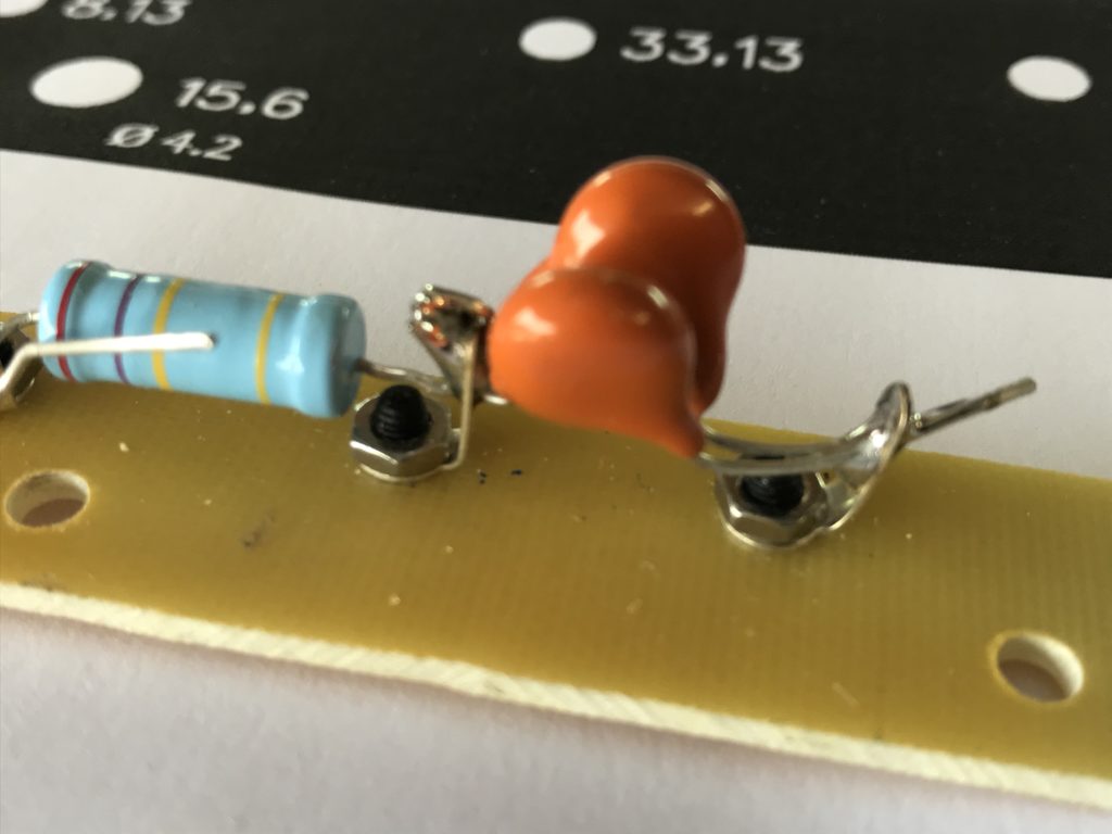
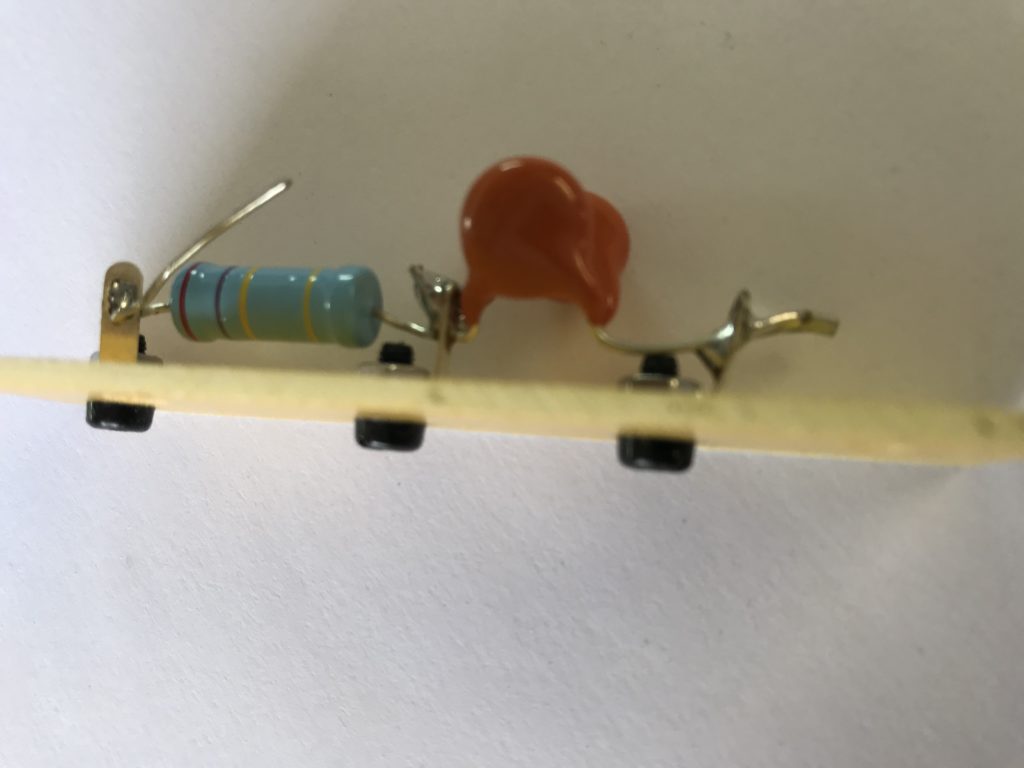
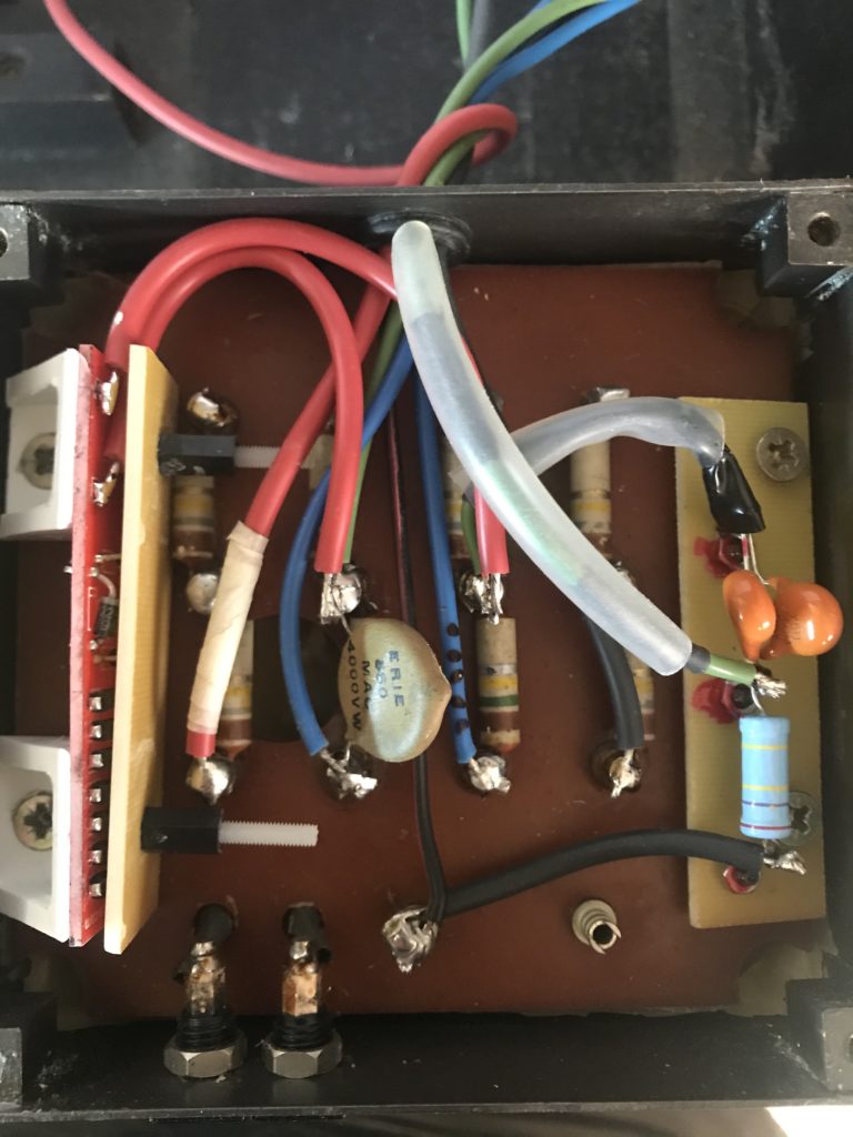
Using high grade components (see parts page), a bare glass fiber board, and nylon screws. Tip: temporary metal screws were used during soldering phase.
Note that new screws are used because existing ones are too short.
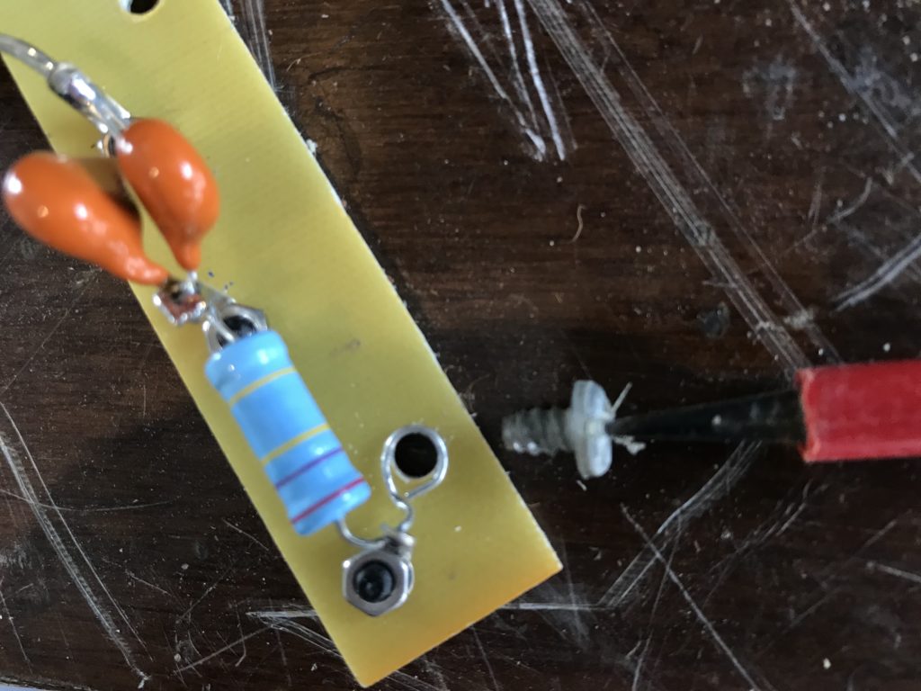
Treble protection board
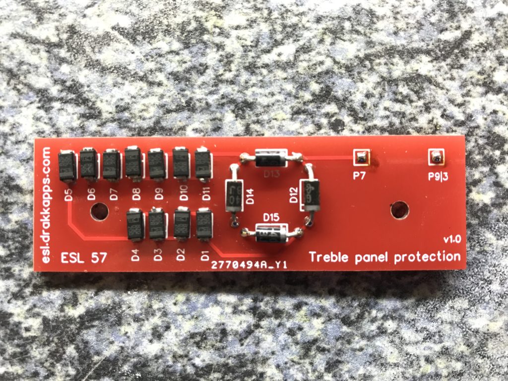
And now something completely different: the treble protection board.
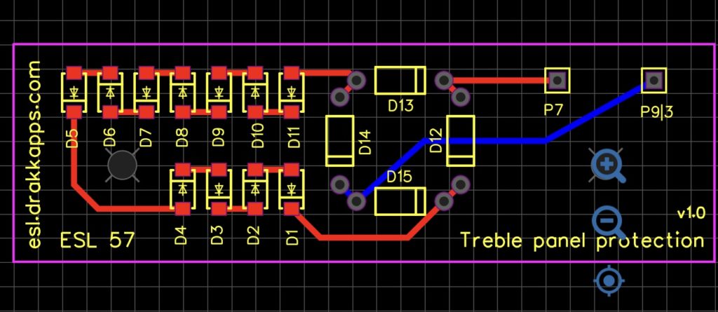
Don’t be afraid: soldering SMD components is not that difficult. Use a multimeter in diode position to check soldering of zener diodes by groups of 4 diodes, to include wiring. Of course, only forward voltage is checked, backward voltage is not reachable. Respect directions otherwise something will rapidly fail.
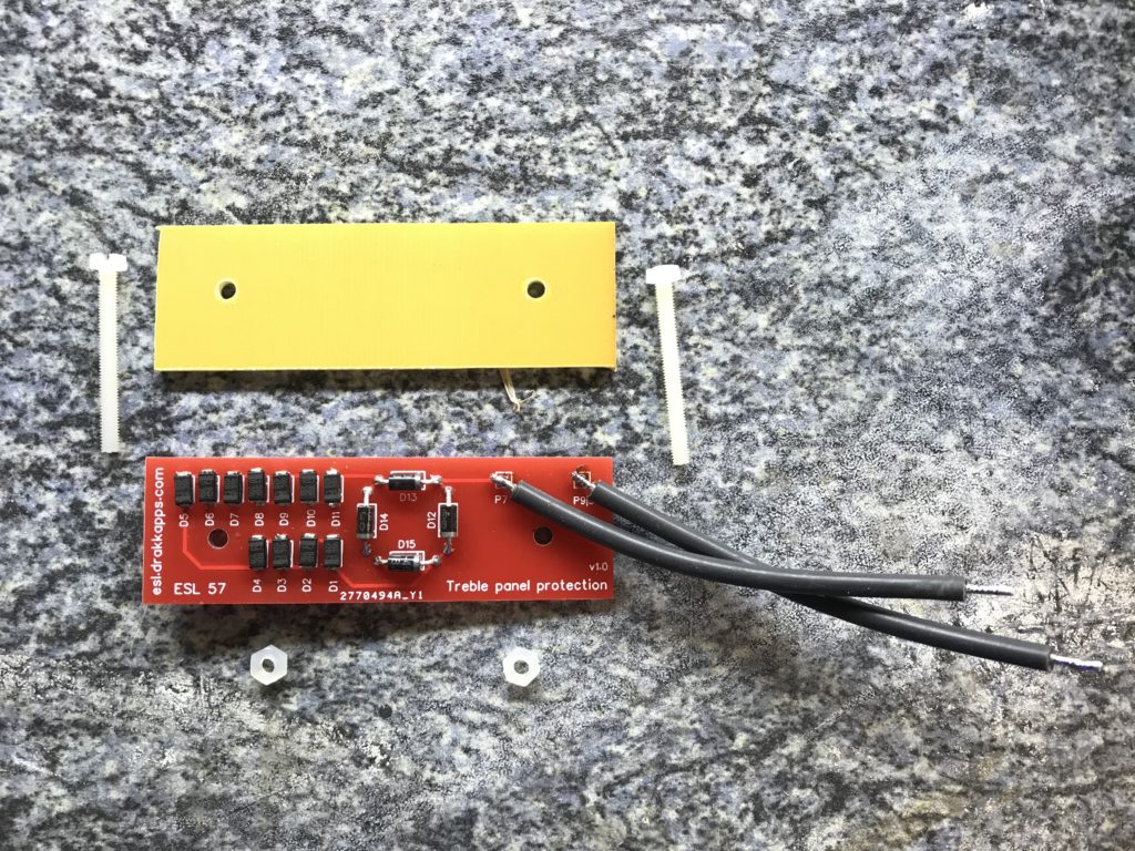
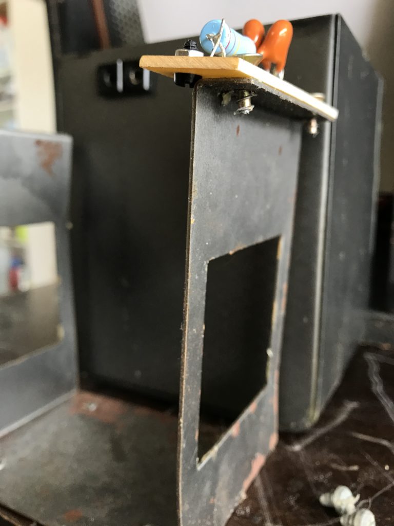
The 2 black wires are 8cm long for a serie 2. For serie 1, the PCB itself is 1mm too high and needs some grinding. Besides, wires need to be longer, 10cm.
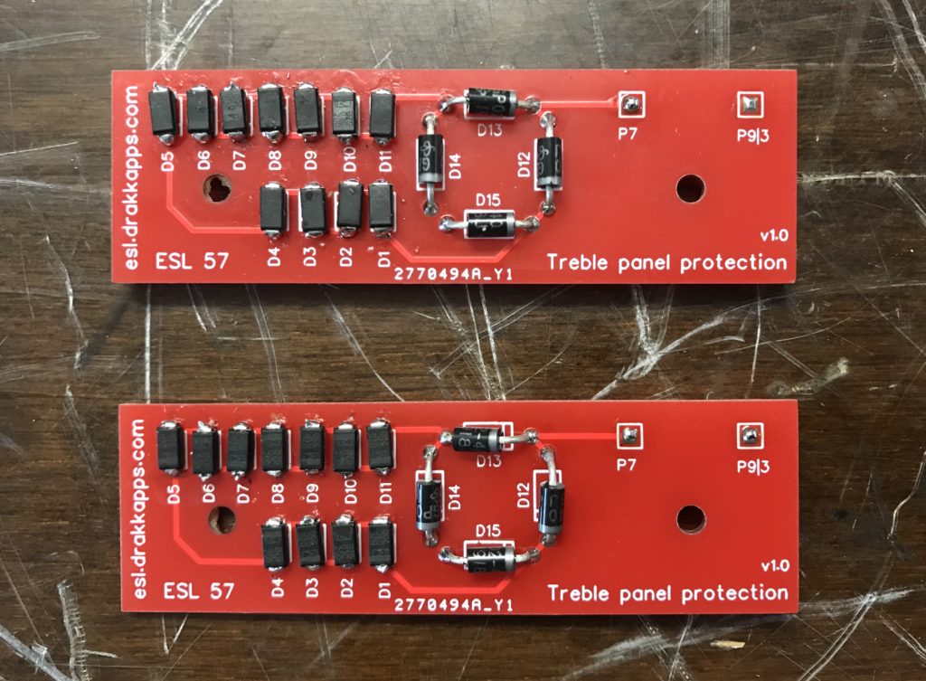
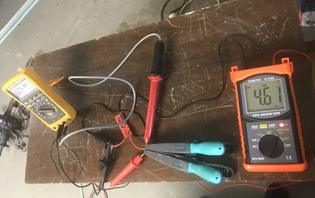
Tip: track any leakage, especially if using soldering compound. Measuring SMDs only (4 full sized diodes not soldered yet), check forward voltage by packets of 5 zener (about 2.5V), then check resistance: about 25MOhm in forward direction for the full loop, >500MOhm in reverse direction. Check resistance of each SMD one by one (2MOhm,>100MOhm). Once diode bridge soldered, resistance measured at wires should stay >500MOhm.
![]()